ESP8266 TX/RX Reader Build Tutorial
This tutorial will guide you through building an ESP8266 TX/RX reader with essential breakout pins for communication, GPIO manipulation, and Over-the-Air (OTA) updates.

Needed Components with eBay Links
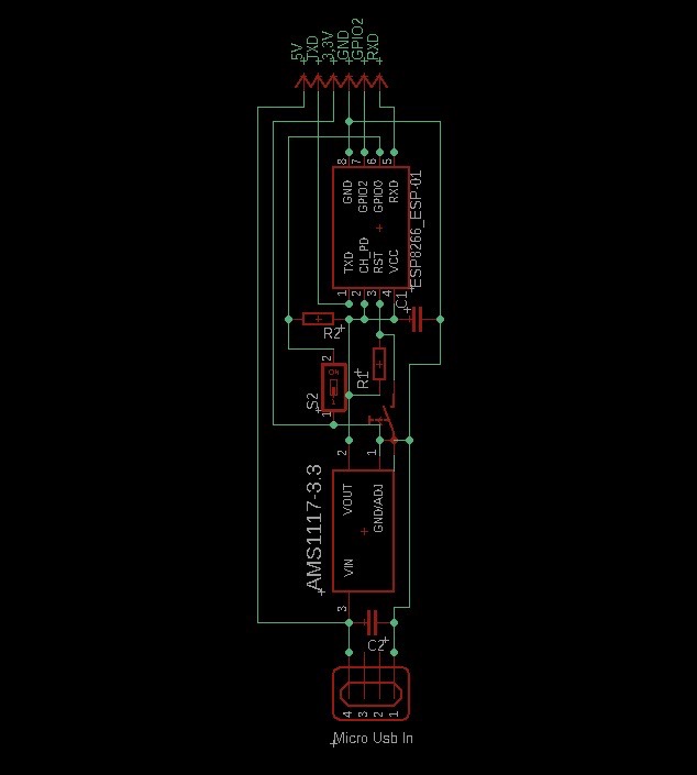
Circuit Diagram
Below is a simple representation of the circuit:

Step-by-Step Instructions
-
Prepare the Base PCB
Start by designing or obtaining a PCB layout that accommodates the ESP8266 module and other components.
-
Solder the ESP8266 Module
Place the ESP8266 module on the PCB and solder its pins. Ensure the pins for RX, TX, VCC, GND, GPIO0, and CH_PD are accessible.
-
Add Resistors
- Connect a 10kΩ resistor as a pull-up resistor between GPIO0 and VCC.
- Connect a 10kΩ resistor as a pull-up resistor between CH_PD and VCC to keep the ESP8266 enabled.
- Connect another 10kΩ resistor as a pull-up resistor for the Reset pin (RST).
-
Install the Toggle Switch and Push Button
- Connect the toggle switch to GPIO0, allowing you to pull it low for programming mode.
- Connect the push button to the Reset pin (RST) for manual resetting.
-
Add Capacitors
- Solder the 47uF electrolytic capacitor across VCC and GND for power stabilization.
- Solder the 104 ceramic capacitor near the ESP8266 module for decoupling.
-
Attach the Pin Header
Connect the pin header to break out RX, TX, GND, 3.3V, 5V, and optionally GPIO2.
-
Connect the Micro-USB Port
Solder the micro-USB port to provide power to the board. Ensure proper polarity and connections for VCC and GND.

-
Test the Board
Power the board using the micro-USB port, and test RX/TX communication with a USB-to-serial adapter or other device.
Uploading the Firmware
First-Time Upload (Before OTA is Enabled)
- Connect the RX and TX pins of the ESP8266 to a USB-to-Serial adapter.
- Connect the TX pin of the ESP8266 to the RX pin of the USB-to-Serial adapter.
- Connect the RX pin of the ESP8266 to the TX pin of the USB-to-Serial adapter.
- Ensure the GND pin of the ESP8266 is connected to the adapter’s GND.
- Set the toggle switch connected to GPIO0 to LOW to enter programming mode.
- Connect 5V power to the ESP8266 through the 5V pin.
- Open the Arduino IDE, select the correct COM port and ESP8266 board type (e.g., “Generic ESP8266 Module”), and upload the firmware.
- Once the upload is complete, set the toggle switch on GPIO0 back to HIGH.
Subsequent Uploads via OTA
Once the firmware is successfully uploaded, subsequent updates can be done wirelessly through the OTA feature. To upload new firmware:
- Ensure the ESP8266 is powered and connected to the same Wi-Fi network as your computer.
- In the Arduino IDE, select the network port corresponding to the ESP8266 (visible under the “Tools > Port” menu).
- Upload the updated firmware wirelessly without reconnecting the RX/TX pins.
Notes
Make sure to double-check all connections before powering the board to avoid damaging the ESP8266 module. Use a multimeter to verify solder joints and continuity.


