Introduction
This tutorial will guide you through building a simple breadboard power supply using a micro USB cable as the power source. An LED will indicate when the circuit is powered.
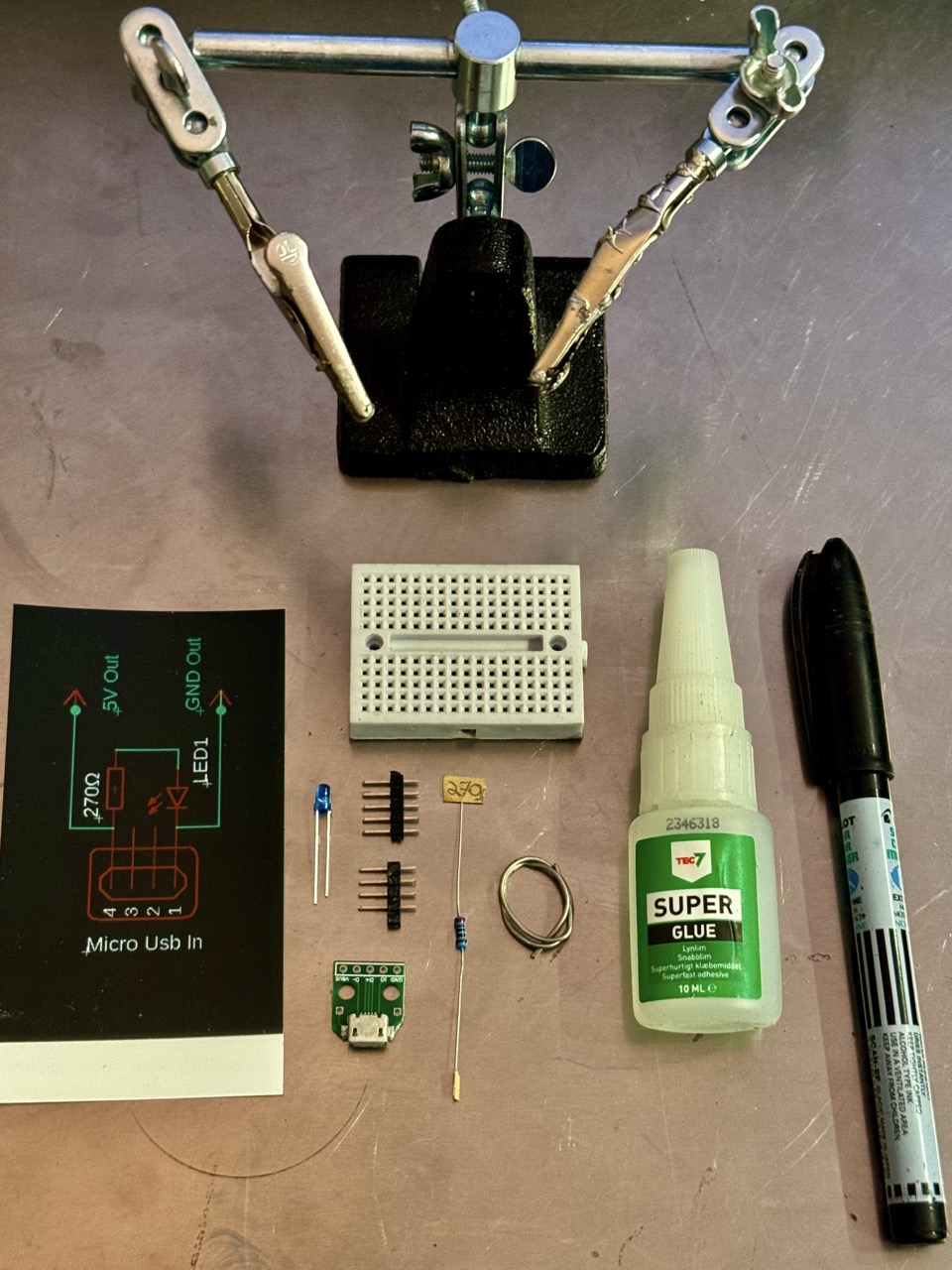
Components Needed with eBay Links
- Micro USB Breakout
- 270Ω Resistor (1/4W)
- Mini Breadboard
- 3mm LED (Blue)
- Male Pin Headers
- Soldering Kit
- Super Glue (optional)
- Black Marker Pen (Optional)
No Ads Available.
Step 1: Circuit Diagram
Below is the schematic of the power supply circuit:
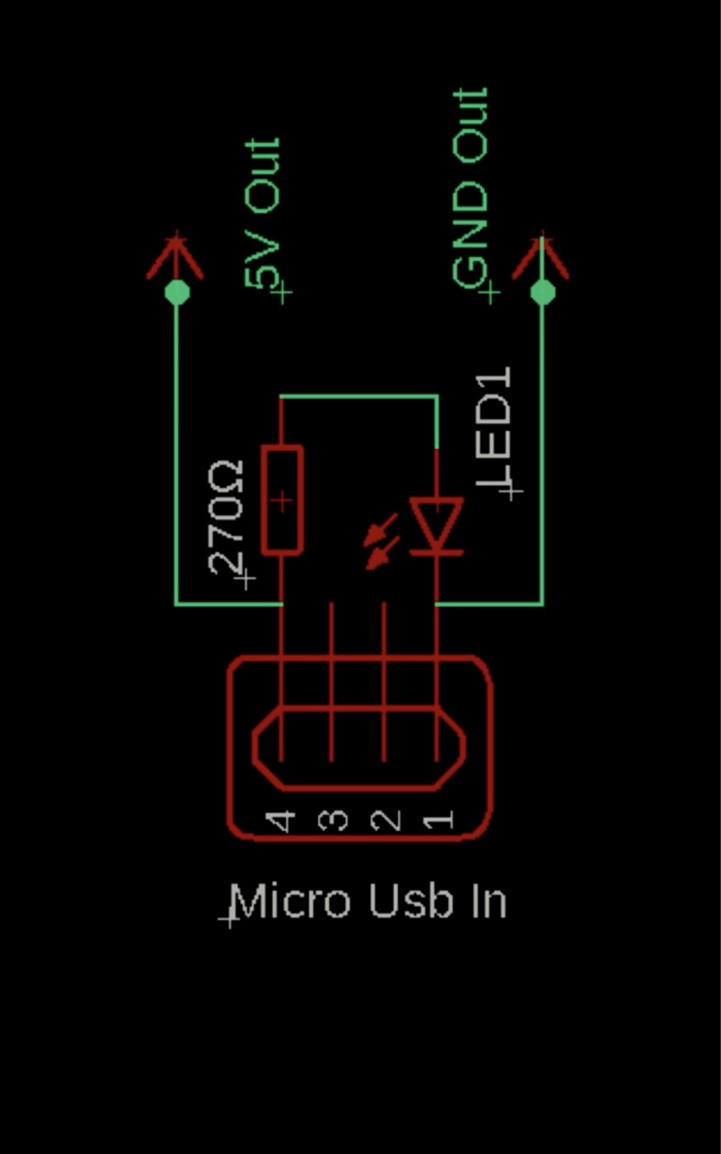
The circuit includes:
- A 270Ω resistor connected to the LED for current limiting.
- A Micro USB module providing power (5V).
- A soldered circuit on the Micro USB module PCB.
Step 2: Building the Circuit
- Prepare the Resistor and LED
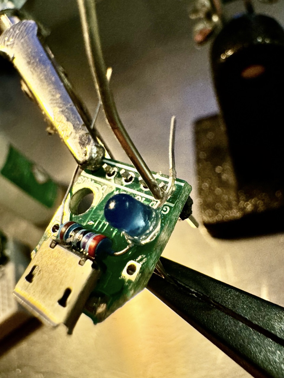
Apply a small amount of glue to fix the 270Ω resistor near the USB module on the Micro USB PCB. Bend one leg of the resistor so it connects to the VCC pin on the module. Guide the other leg of the resistor through the mounting hole near the GND pin, positioning it toward where the LED will be placed.
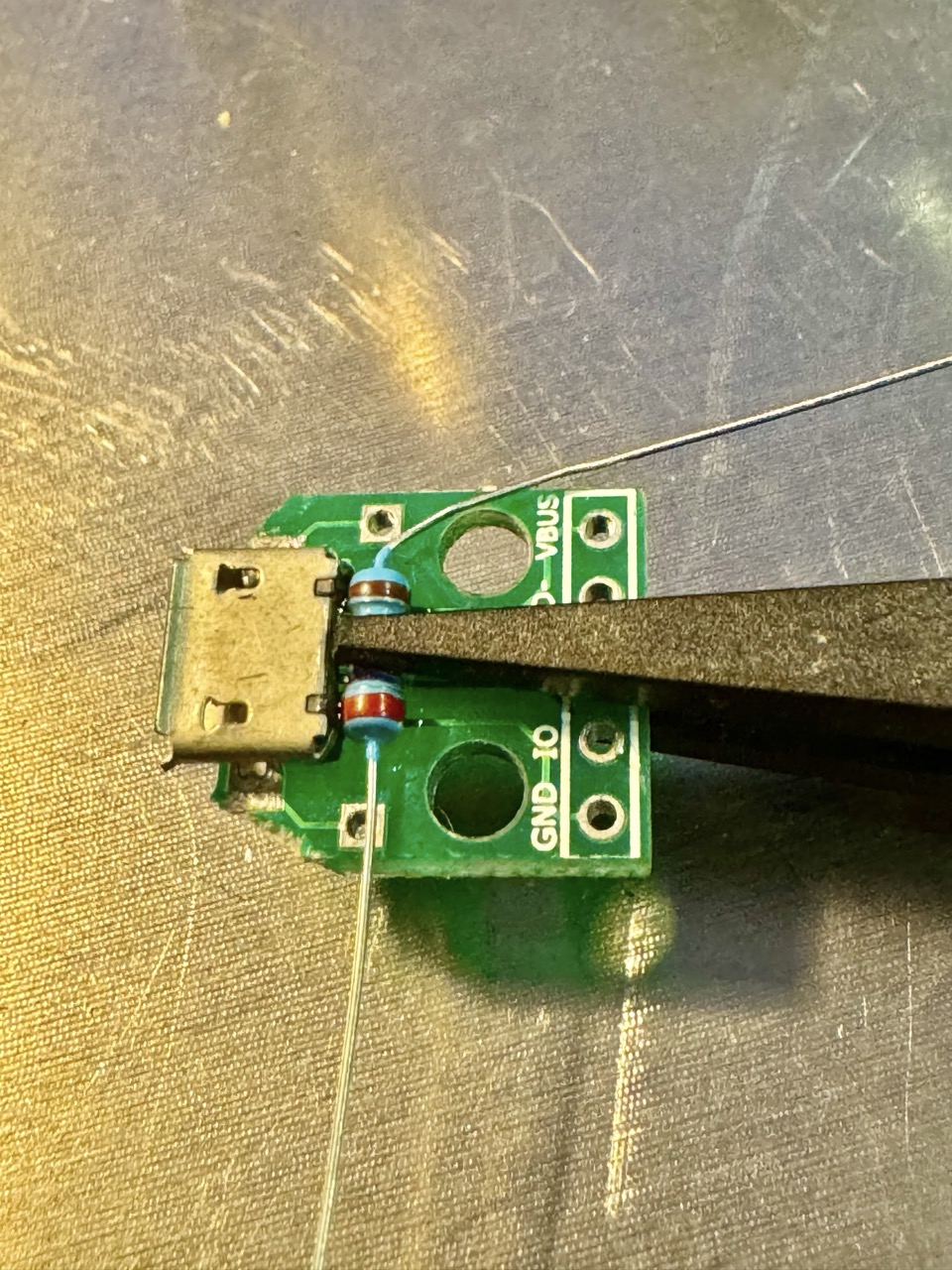
Next, bend the longer leg (anode) of the LED at a 90° angle so it aligns with the GND pin of the Micro USB module. Insert the shorter leg (cathode) of the LED through the mounting hole to twist and connect with the resistor leg. Adjust the bent anode to ensure it is properly positioned near the GND pin for easy soldering.
- Solder Pin Headers
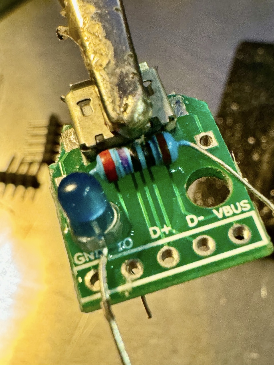
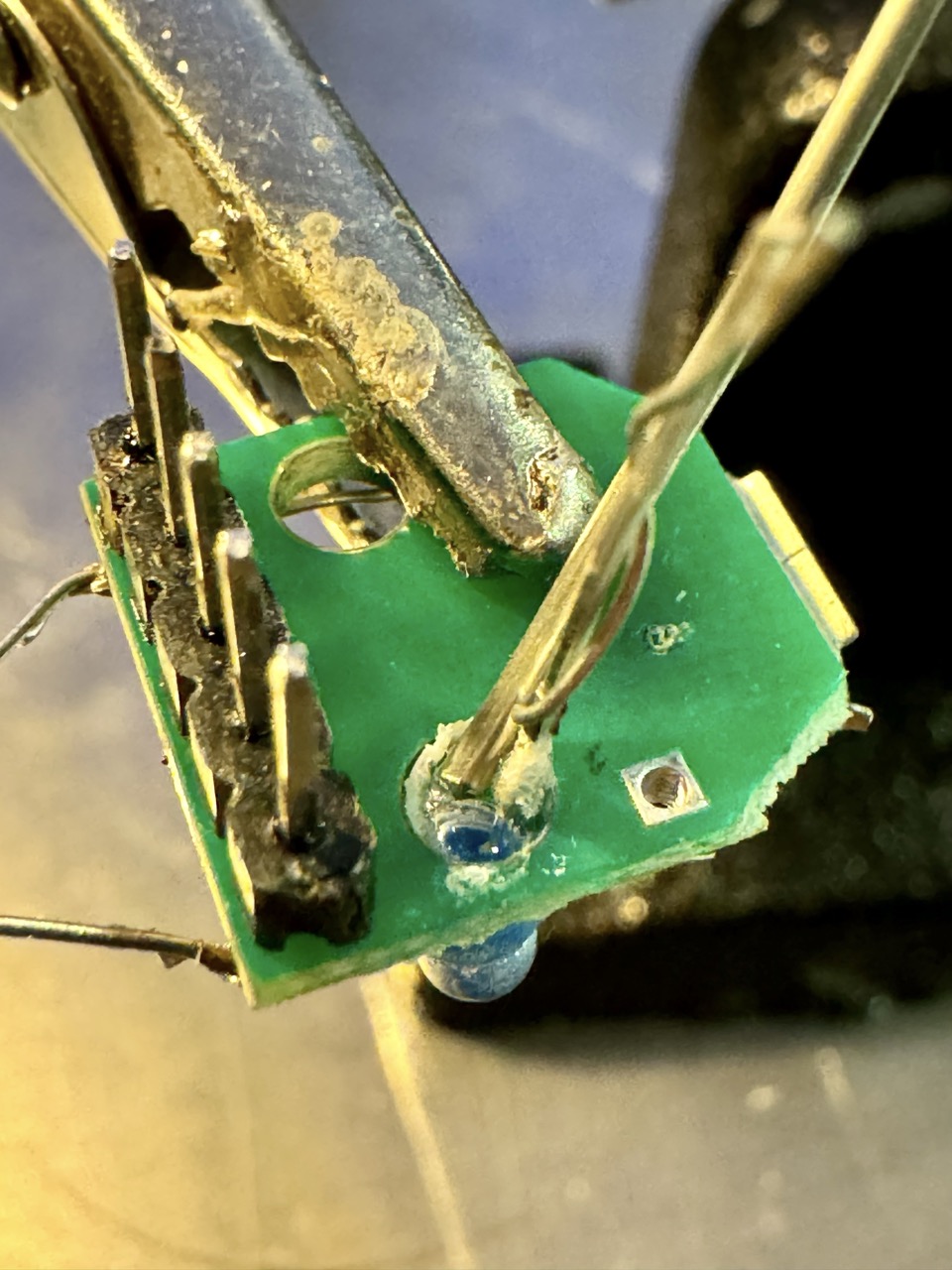
Insert male pin headers into the PCB and solder them from the front side. This ensures stable connections for the VCC and GND pins to the breadboard.
- Solder the Resistor and LED
From the back of the PCB, solder the twisted resistor leg and LED cathode (shorter pin) together. Then solder the free leg of the resistor to the VCC pin and the longer LED leg (anode) to the GND pin. Trim any excess pin lengths for a clean finish.
- Spacer and Coloring
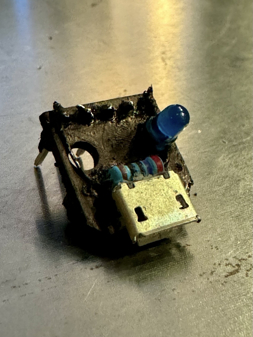
Glue a second pin header (with its pins removed) to the PCB to act as a spacer, providing stability when the board is mounted onto a breadboard. Once the glue dries, use a black marker to color the board for a polished look.
- Test the Circuit
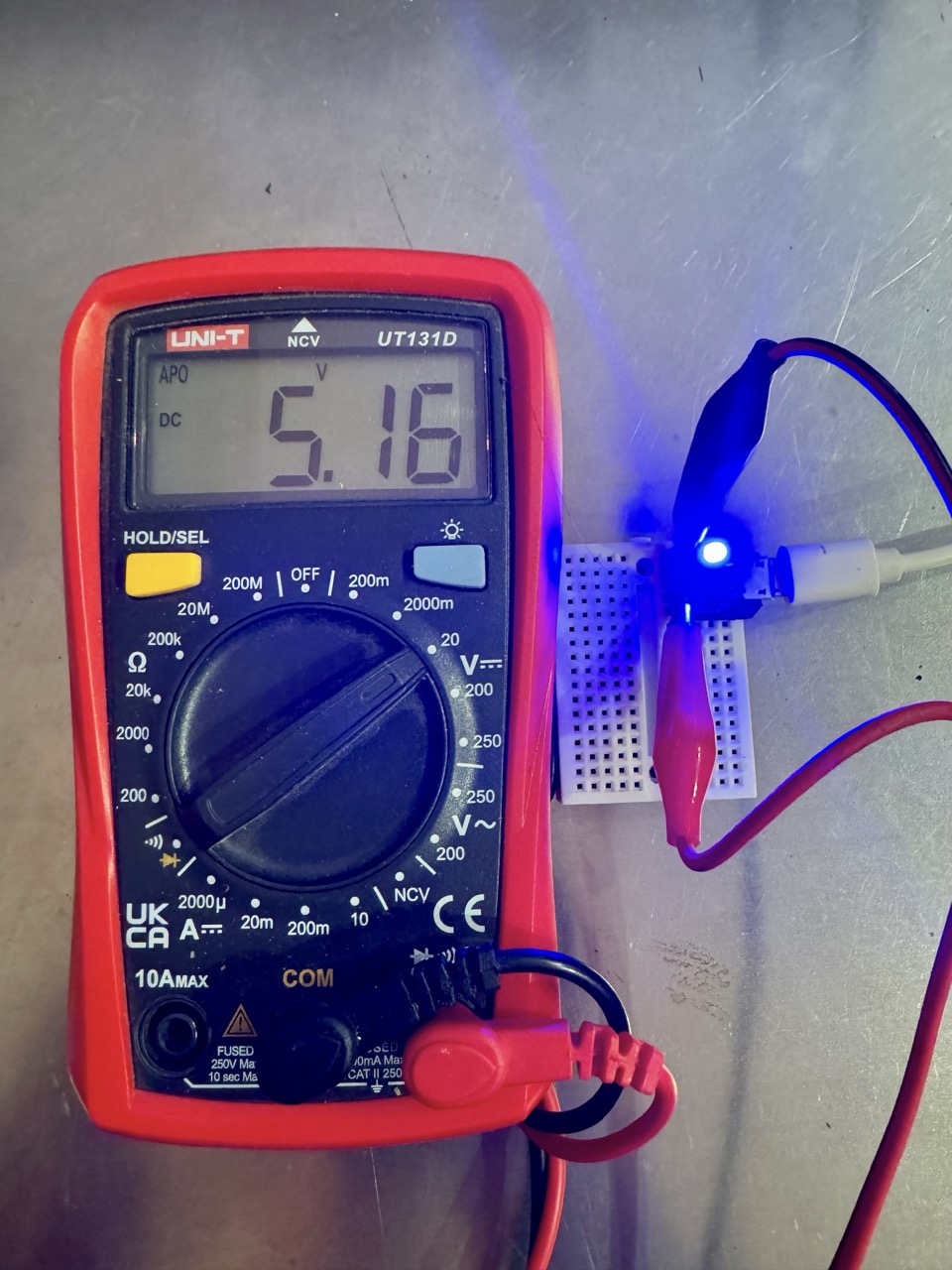
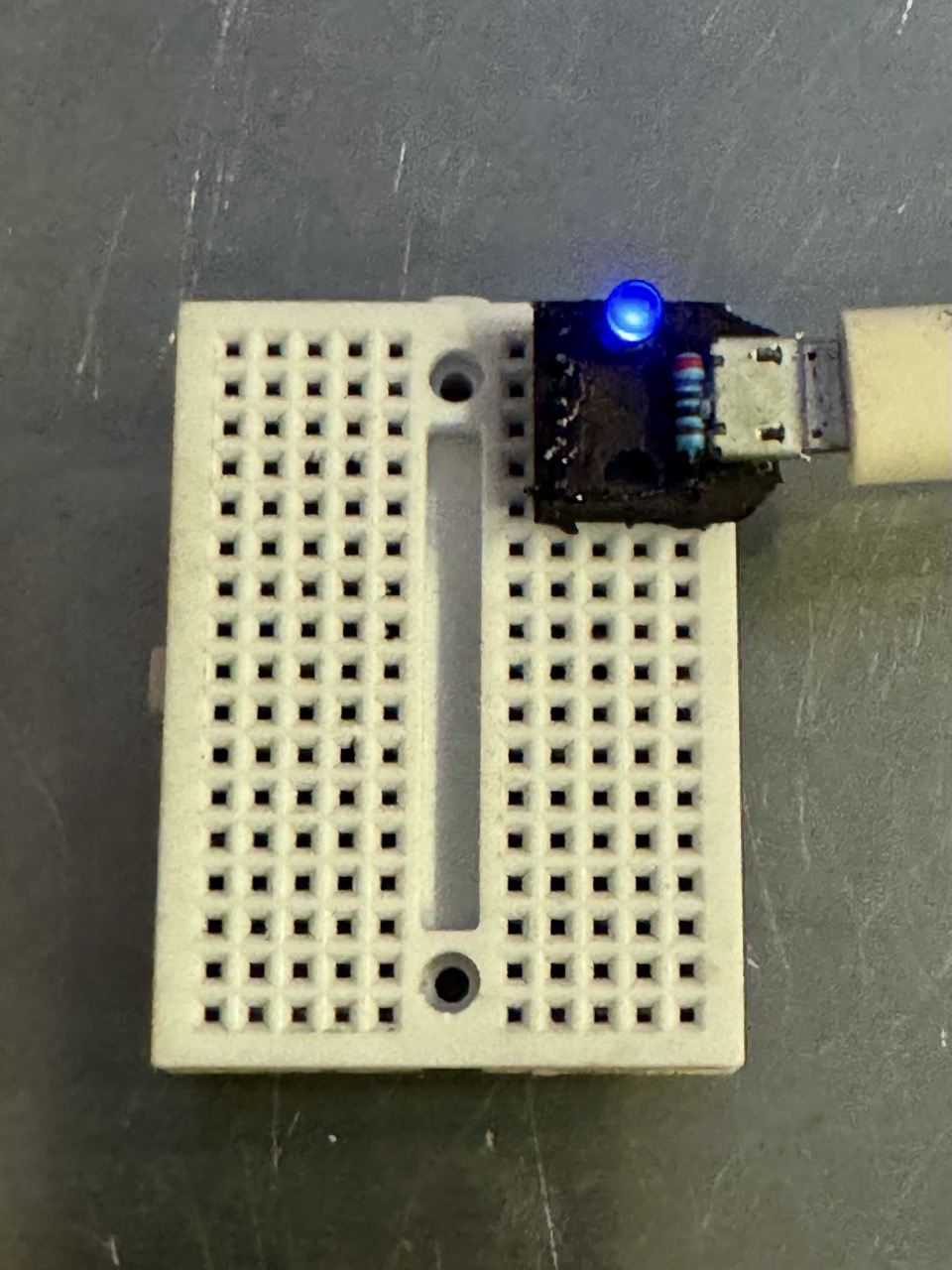
Connect a Micro USB cable to the breakout module and plug it into a power source, such as a phone charger or laptop. The LED should light up, confirming the circuit is complete and functioning properly.
- Optional: Add a Multimeter
Use a multimeter to verify that the VCC and GND pins are delivering a stable 5V output. This step ensures the setup is ready for powering future components.
Step 3: Troubleshooting
- If the LED doesn't light up, check the polarity of the LED and USB cable connections.
- Verify that the USB power source is working.
- Double-check resistor values to ensure proper current limiting.
Conclusion
Congratulations on successfully building a simple breadboard power supply! This setup is perfect for powering small circuits or prototyping projects, and the LED indicator ensures you can quickly verify when the circuit is powered. By completing this project, you've gained hands-on experience in soldering and working with basic electronic components, which are crucial skills in electronics.
Expand your skills by exploring circuits with active components like transistors, diodes, and ICs. These enable advanced projects such as amplifiers and IoT systems.
Get started with an 2200 pcs Electronic Component Assortment Kit or an Mega Electronic Component Kit from amazon to explore a wide varity of electronic component types. Pair them with your power supply for building all sorts of circuits and experiments.
Master measurement techniques with our Introduction to Measuring guide, covering tools like multimeters and oscilloscopes.
New to electronics? Check out this free electronics book for clear explanations and practical examples.
Practice your skills with 100s of breadboard experiments available on our site and continue exploring the exciting world of electronics!


