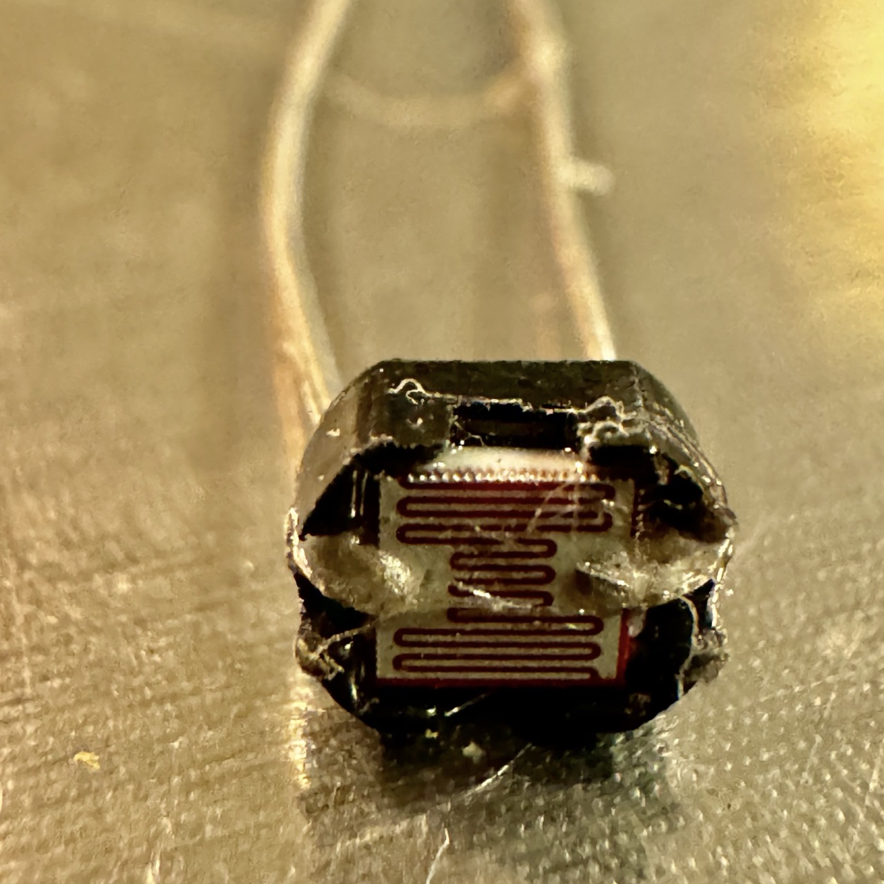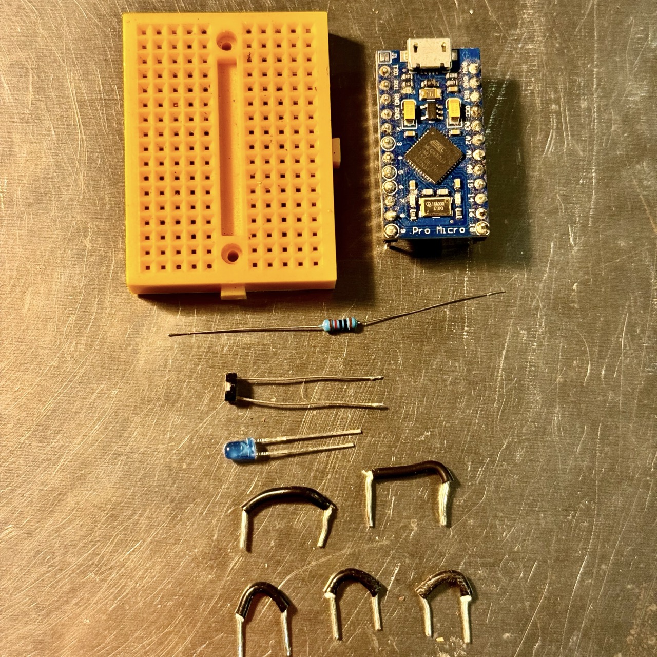

The aim of this experiment is to explore the behavior of a Light Dependent Resistor (LDR) by measuring its resistance under different lighting conditions and using it to sense light levels in a circuit.


An LDR is a resistor whose resistance decreases with increasing light intensity. In the dark, the LDR has high resistance, and in bright light, it has low resistance. This property makes LDRs useful in circuits where light sensing is needed, such as in automatic street lights, alarm systems, or light meters.

In this experiment, the LDR and a fixed resistor (10kΩ) form a voltage divider. The output voltage at the junction between the LDR and resistor changes with light intensity, allowing us to measure light levels.
1. Connect the LDR and 10kΩ resistor in series on the breadboard, forming a voltage divider.
2. Connect one end of the LDR to 5V (or the positive terminal of the battery), and the other end to the resistor.
3. Connect the free end of the 10kΩ resistor to ground.
4. Measure the voltage at the junction between the LDR and the resistor using a multimeter or Arduino analog input pin.
5. Vary the lighting conditions and observe the voltage or resistance change.
const int ldrPin = A0; // LDR connected to A0
int ldrValue = 0;

void setup() {
  Serial.begin(9600); // Begin serial communication
}

void loop() {
  ldrValue = analogRead(ldrPin); // Read the analog value from LDR
  Serial.print("LDR Value: ");
  Serial.println(ldrValue); // Print the value to the serial monitor
  delay(500); // Wait for 500ms
}
As you change the light intensity on the LDR, observe how the output voltage varies. In low light, the voltage should be lower, while in bright light, the voltage should increase. The voltage divider converts the changing resistance of the LDR into a measurable voltage that can be used in a circuit to sense light levels.
This experiment demonstrates the use of an LDR in detecting light levels. The varying resistance of the LDR under different lighting conditions is converted into a measurable voltage through a voltage divider circuit. This simple sensor can be used in numerous light-based applications such as automatic lighting systems or light meters.