
Understanding Capacitor Types
Capacitors are fundamental components in electronics, storing and releasing electrical energy based on their construction, materials, and intended use. Here’s an overview of the most common types:
- Ceramic Capacitors: Known for their stability and small size, these non-polarized capacitors excel in high-frequency applications like noise filtering and decoupling in microcontrollers or RF circuits.
- Electrolytic Capacitors: These polarized capacitors offer high capacitance values, making them ideal for power supply smoothing and energy storage in audio amplifiers or DC-DC converters.
- Tantalum Capacitors: Compact and stable, tantalum capacitors are used in precision circuits, such as medical devices or aerospace electronics, where reliability is paramount. They are also polarized.
- Film Capacitors: With excellent tolerance and low noise, these are preferred for audio crossovers, signal coupling, and low-frequency filtering in analog circuits.
- Supercapacitors: Emerging in modern designs, these offer extremely high capacitance (Farads) for energy storage in renewable energy systems or backup power applications.
Each type has unique strengths, so understanding your project’s needs is the first step in selection.
Key Factors in Choosing a Capacitor
Choosing a capacitor requires careful consideration of several electrical and environmental factors. Here’s a detailed breakdown:
- Capacitance Value: Measured in Farads (F), this determines how much charge a capacitor can store.
- For decoupling: A 0.1 µF ceramic capacitor (marked
104) is a standard choice for filtering high-frequency noise near ICs. - For power smoothing: Electrolytic capacitors ranging from 10 µF to 1000 µF stabilize voltage in power rails.
- For timing circuits: Values like 1 nF to 10 µF are common in RC networks.
- For decoupling: A 0.1 µF ceramic capacitor (marked
- Voltage Rating: The maximum voltage a capacitor can handle without breaking down.
- Rule of thumb: Select a rating 1.5 to 2 times your circuit’s operating voltage (e.g., 10V rating for a 5V circuit).
- High-voltage applications (e.g., 400V in AC-DC converters) may require specialized film or electrolytic capacitors.
- ESR (Equivalent Series Resistance): Lower ESR improves efficiency in high-speed circuits like switching regulators. Tantalum and ceramic capacitors typically have lower ESR than electrolytics.
- Temperature Rating: Capacitors degrade at extreme temperatures. Choose ratings like -40°C to +105°C for industrial use or +125°C for automotive applications.
- Tolerance: Indicates precision. Ceramic capacitors may have ±10% tolerance, while film capacitors can offer ±1% for critical applications.
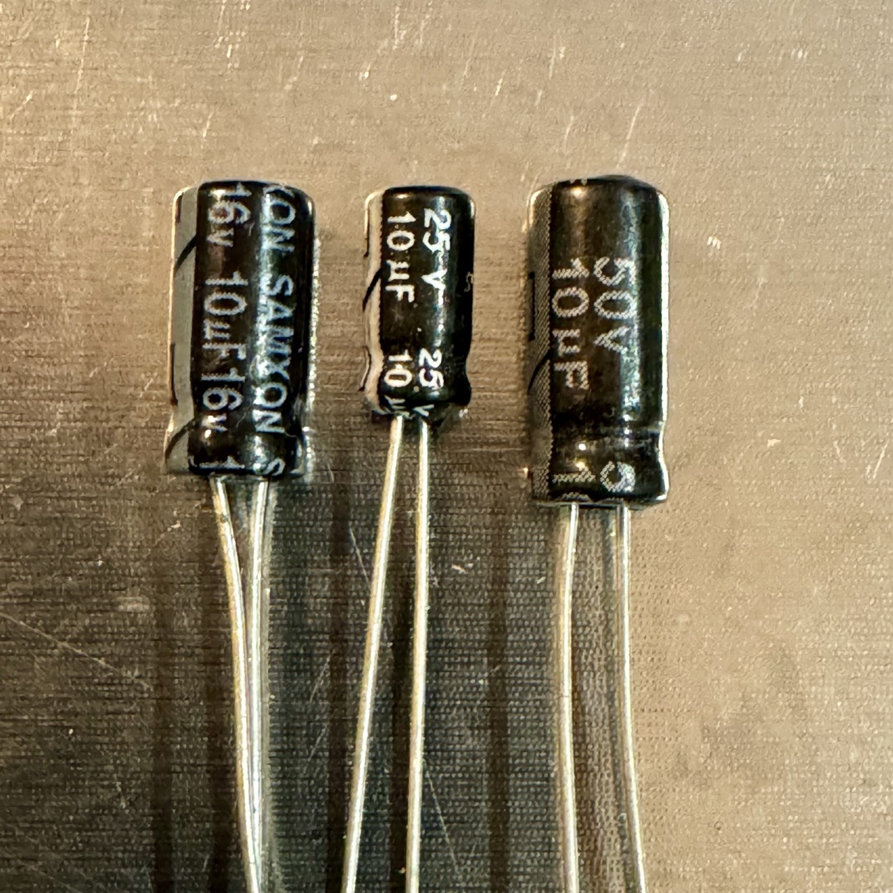
The image compares three 10 µF electrolytic capacitors:
- 10 µF 16V: Larger than the 25V version due to design trade-offs.
- 10 µF 25V: The smallest, balancing size and voltage capacity.
- 10 µF 50V: The largest, built for higher voltage resilience.
This demonstrates how voltage ratings affect size—a critical factor in space-constrained designs like wearables or IoT devices.
No Ads Available.
Ceramic vs. Electrolytic Capacitors
Two of the most widely used capacitor types—ceramic and electrolytic—differ significantly. This comparison helps clarify their roles:
| Feature | Ceramic | Electrolytic |
|---|---|---|
| Capacitance Range | pF to a few µF | µF to thousands of µF |
| Voltage Rating | Lower (e.g., 6V–50V) | Higher (e.g., 25V–500V) |
| Polarity | Non-Polarized | Polarized |
| Size | Smaller | Larger |
| ESR | Very Low | Higher |
| Use Case | High-frequency filtering, decoupling | Bulk power smoothing, energy storage |
| Lifespan | Longer (no electrolyte to dry out) | Shorter (electrolyte degrades over time) |
Common Applications
Capacitors serve diverse purposes across electronics. Here are practical examples:
| Application | Recommended Capacitor | Notes |
|---|---|---|
| Power Supply Smoothing | 10 µF - 1000 µF Electrolytic | Reduces ripple in AC-DC conversion. |
| Decoupling | 0.1 µF Ceramic (104) | Placed near ICs to filter noise. |
| Voltage Stabilization | 10 µF Electrolytic + 0.1 µF Ceramic | Parallel combination for broad-spectrum filtering. |
| Signal Coupling | Film Capacitor, 1 µF - 10 µF | Blocks DC while passing AC signals. |
| Timing Circuits | 1 nF - 100 nF Ceramic or Film | Used in oscillators or 555 timer circuits. |
Practical Tips for Selection
Beyond specs, real-world considerations can optimize your capacitor choice:
- Check Datasheets: Look for derating curves and ESR values specific to your operating conditions.
- Avoid Over-Sizing: Excessively high voltage ratings increase cost and size without benefit.
- Test in Circuit: Prototype with different capacitors to verify performance, especially for noise-sensitive designs.
- Mind Polarity: Reverse-connecting a polarized capacitor (e.g., electrolytic) can cause failure or explosion.
- Storage Conditions: Store electrolytic capacitors in cool, dry environments to prevent degradation before use.
Conclusion
Selecting the right capacitor is a blend of science and practicality. By matching capacitance, voltage, ESR, and type to your circuit’s demands, you ensure reliability and efficiency. Experimentation and datasheet analysis can further refine your choice, empowering you to tackle projects from simple hobby builds to complex industrial systems.