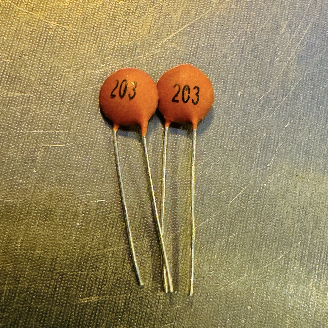
Introduction
Ceramic capacitors are passive electronic components commonly used for filtering, bypassing, and coupling signals in circuits. They store electric charge and are valued for their high stability, reliability, and ability to operate at high frequencies. Ceramic capacitors are widely used in various electronic applications due to their small size, low cost, and versatile performance.
Description
Ceramic capacitors consist of a ceramic dielectric material sandwiched between two conductive plates. The dielectric material determines the capacitance value and other properties of the capacitor. These capacitors are usually non-polarized, meaning they can be connected in any direction, making them flexible and easy to use in AC and DC circuits. They are commonly used for applications like filtering, decoupling, and timing in electronic
Specifications
- Capacitance Range: Typically from a few picofarads (pF) to several microfarads (μF).
- Voltage Rating: Ceramic capacitors may not have the voltage rating printed on them, so check the datasheet or packaging if available. Common voltage ratings include 50V, 100V, and 500V.
- Temperature Coefficient: Stability across temperature varies based on type (e.g., Class I or Class II ceramic).
- Dielectric Material: Types include NP0 (C0G), X7R, Y5V, and others, each with different stability characteristics.
Types of Ceramic Capacitors
- Class I: High stability and low loss, ideal for resonant circuits. Common types include NP0 (C0G) capacitors.
- Class II: Moderate stability, higher capacitance per volume, typically used in filtering and bypassing applications. Includes X7R and Y5V capacitors.
Applications
- Filtering: Ceramic capacitors are used to filter out unwanted frequencies in power supplies and signal lines.
- Decoupling/Bypassing: Help stabilize voltage by providing a reservoir for short bursts of energy, useful for microcontrollers and digital circuits.
- Coupling: Passes AC signals between stages of amplifiers while blocking DC components.
- Resonant Circuits: Class I capacitors, with their stability, are suitable for frequency-selective circuits.
Advantages and Disadvantages
Advantages
- High stability and reliability
- Wide range of capacitance values
- Low cost and compact size
- Non-polarized, suitable for AC and DC applications
Disadvantages
- Limited capacitance range compared to other types like electrolytic capacitors
- Some types have temperature-dependent capacitance changes
- Class II and III capacitors may have higher losses
Ceramic Capacitor Markings and How to Read Values
Ceramic capacitors often have a three-digit code that represents their capacitance value. Here’s how to interpret these markings:
Common Markings:
- Two-digit marking (e.g., "33"): This directly represents the capacitance in picofarads (pF). For example, "33" means 33 pF.
- Three-digit marking (e.g., "104"): The first two digits are significant figures, and the third digit is a multiplier in powers of ten.
Example: "104" means:
- First two digits: 10
- Third digit (4) is a multiplier: 10,000 (104)
- Result: 10 x 10,000 = 100,000 pF = 0.1 µF
Quick Reference Table:
| Marking | Capacitance (pF) | Capacitance (nF) | Capacitance (µF) |
|---|---|---|---|
| 10 | 10 pF | - | - |
| 47 | 47 pF | - | - |
| 101 | 100 pF | 0.1 nF | - |
| 104 | 100,000 pF | 100 nF | 0.1 µF |
| 472 | 4700 pF | 4.7 nF | - |
| 223 | 22,000 pF | 22 nF | 0.022 µF |
Tolerance Codes for Ceramic Capacitors
Tolerance shows how close the actual capacitance value is to the marked value. Some common tolerance codes:
- F: ±1%
- G: ±2%
- J: ±5%
- K: ±10%
- M: ±20%
Example: A marking of "104K" indicates a 100,000 pF (0.1 µF) capacitor with a ±10% tolerance.
Using Ceramic Capacitors in a Circuit
To use a ceramic capacitor in a circuit, connect it as specified in the circuit diagram. Since they are non-polarized, the orientation doesn’t matter.
Example Circuit: For noise filtering, place a 100 nF (0.1 µF) capacitor across the power (VCC) and ground (GND) pins of a microcontroller to reduce noise and improve stability.
How to Test a Capacitor
Testing a capacitor helps verify its capacitance, check for shorts, or detect leaks. Here are some methods:
1. Using a Multimeter (Capacitance Mode)
- Set the Multimeter: Select the capacitance mode.
- Discharge the Capacitor: Discharge before testing.
- Connect Leads: Attach multimeter leads to capacitor terminals.
- Read Measurement: Compare displayed value with rated capacitance.
2. Using an LCR Meter
- Set the Meter: Select capacitance mode on LCR meter.
- Discharge Capacitor: Discharge before testing.
- Connect Leads: Attach probes to capacitor leads.
- Read Result: Compare to rated capacitance.
3. Testing Electrolytic Capacitors for Leakage
- Multimeter in Resistance Mode: If resistance stays low, capacitor may be leaking.
- Using ESR Meter: Higher-than-expected ESR indicates a bad capacitor.
4. Testing for Shorted Capacitors
In continuity or resistance mode, if the multimeter shows low resistance, the capacitor may be shorted.
5. Visual Inspection
Check for physical signs of damage, like bulging, leaks, or burn marks.
Note: Always discharge capacitors before testing to avoid injury or damage.
Conclusion
Ceramic capacitors are versatile, reliable, and widely used in electronic circuits. With a variety of types available, they suit applications from simple filtering to precise resonant circuits. Understanding their specifications and usage can enhance circuit design and performance in various electronic projects.
