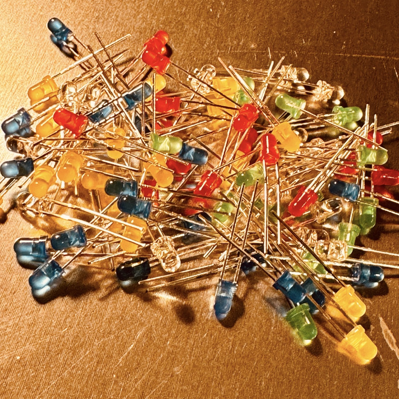
LED Indicator Experiment


This experiment demonstrates how to use LEDs (Light Emitting Diodes) as simple indicators in electronic circuits. LED indicators are commonly used to signal power status, input, or output conditions in a circuit.
To build a basic circuit with LED indicators that show the state of an input, using resistors to limit current and prevent LED damage.

Note: Ensure the correct polarity when connecting LEDs; the longer leg (anode) should connect to the positive side of the power supply, and the shorter leg (cathode) to the ground.
Once connected, each LED should light up, indicating power flow through the circuit. Try varying the input voltage (e.g., by replacing the 9V battery with a lower voltage supply) to observe the brightness change.
Observe the brightness of each LED. If the voltage applied is sufficient, the LEDs will light up, showing a visual indication of circuit status. With lower voltages, the LEDs may dim or fail to light up, as each LED has a specific forward voltage threshold.
LEDs are diodes that emit light when current flows through them in the forward direction. The resistor prevents excessive current, protecting the LEDs from damage. The LED's brightness depends on the current flow, which is influenced by the resistor value and the applied voltage.
This experiment demonstrates how LEDs can be used as visual indicators in circuits, providing feedback on power or signal presence. LEDs are widely used in electronics for their simple operation and energy efficiency.