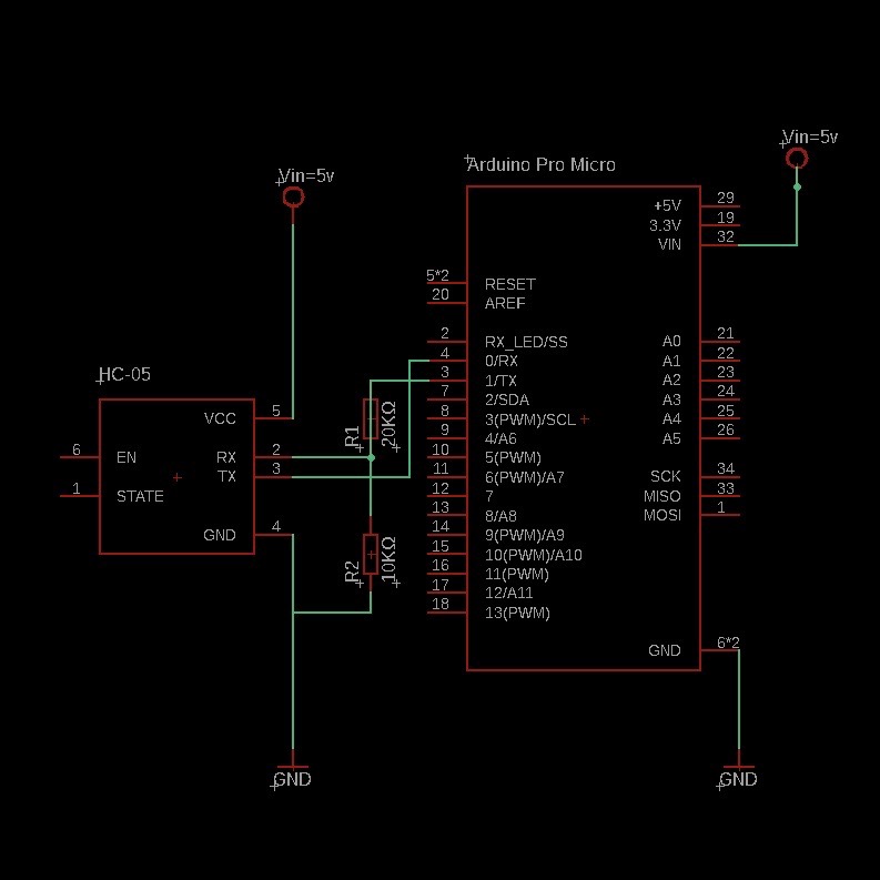
Circuit Diagram
The voltage divider reduces the 5V logic level from the microcontroller's TX pin to 3.3V, which is compatible with the HC-05's RX pin.

This guide explains how to use a voltage divider to safely connect a 5V microcontroller to a 3.3V HC-05 Bluetooth module.
To understand how to use a voltage divider to step down a 5V TX signal from a microcontroller to a 3.3V level suitable for the HC-05 module.
The voltage divider reduces the 5V logic level from the microcontroller's TX pin to 3.3V, which is compatible with the HC-05's RX pin.

The HC-05 module operates at 3.3V logic levels and cannot tolerate 5V signals directly on its RX pin. A voltage divider is used to step down the 5V signal from the microcontroller to a safe level:
V_out = V_in * (R2 / (R1 + R2))
For example, with R1 = 20kΩ and R2 = 10kΩ, the output voltage is:
V_out = 5V * (10k / (20k + 10k)) = 3.3V
This ensures the HC-05 module receives a signal within its voltage tolerance range.
Use the following Arduino code to send and receive serial data with the HC-05 module:
void setup() {
    Serial.begin(9600); // Communication with HC-05
    Serial.println("HC-05 Test");
}

void loop() {
    if (Serial.available()) {
        char data = Serial.read(); // Read data from HC-05
        Serial.print("Received: ");
        Serial.println(data);
    }
}
Open the Arduino IDE's Serial Monitor to observe the communication between the microcontroller and HC-05 module.
Test the circuit by sending data to the HC-05 module from a Bluetooth-enabled device (e.g., a smartphone). Verify that the data is correctly received and displayed in the Serial Monitor.
This experiment demonstrates how to use a voltage divider to safely interface a 5V microcontroller with a 3.3V HC-05 Bluetooth module for serial communication. The voltage divider ensures proper signal levels, protecting the module from damage.