Measuring Instruments for Electronics
Measuring instruments are the backbone of precision and reliability in electronics. These indispensable tools enable you to analyze circuits, test components, and ensure optimal functionality across your projects. Whether you're diagnosing faults, verifying performance, or conducting detailed measurements, understanding these instruments is essential for success. In this guide, we’ll explore the most commonly used measuring tools, explain their practical applications, and provide key formulas to enhance your proficiency and confidence in using them effectively.
Types of Measuring Instruments
1. Multimeter
A multimeter is a versatile tool used for measuring voltage (V), current (I), and resistance (R). It can also test diodes and continuity in a circuit. Digital multimeters are common, providing a numerical display, while analog multimeters have a needle that moves across a scale.

How to measure voltage with a multimeter:
- Set the dial to the appropriate voltage setting, typically denoted by "V". For DC measurements, look for "V⎓" and for AC, "V∿". Ensure you're measuring in the correct voltage range.
- Connect the black probe (COM) to the ground or negative side of the circuit, and the red probe (VΩmA) to the point where you want to measure the voltage.
- Read the value on the display. The voltage should appear as a positive or negative number depending on the polarity of the probes.
Example: Measuring the voltage of a wall socket, you set the multimeter to "V~" (for AC voltage) and carefully insert the probes into the socket slots. The multimeter shows around 120V (or 230V, depending on your region).
AstroAI Digital Multimeter – Buy your Multimeter at AmazonUsing Battery Test Mode on a Multimeter:
- Set the Dial: Turn the dial to "1.5V," "9V," or "BAT" mode, depending on your battery type:
- 1.5V Mode: For AA, AAA, C, or D batteries.
- 9V Mode: For 9V batteries.
- 12V Mode (if available): For 12V batteries.
- Connect Probes: Attach the black probe to the battery’s negative (-) terminal and the red probe to the positive (+) terminal.
- Read the Display:
- 1.5V Batteries: A reading near 1.5V is good; below 1.1V indicates weakness.
- 9V Batteries: A reading near 9V is good; below 6V suggests the battery is low.
- 12V Batteries: A reading near 12V indicates a full charge; below 10V suggests it needs recharging or replacing.
This mode applies a small load, providing a more accurate indication of battery health.
2. Oscilloscope
An oscilloscope is used to observe changing signal voltages in a circuit, displayed as a waveform on the screen. It’s essential for analyzing time-varying signals like AC or digital pulses. Oscilloscopes can display voltage over time, allowing you to measure important parameters such as frequency, amplitude, and signal shape.

How to Measure Voltage and Frequency with an Oscilloscope:
- Connect the oscilloscope probes to the circuit. Attach the ground clip to the circuit ground and the signal probe to the measurement point.
- Set the vertical scale (volts/division) appropriately. For example, use 1V/division for a 5V signal.
- Adjust the time base (seconds/division) to fit the waveform. A smaller time base zooms in, while a larger one shows more cycles.
- Observe the waveform on the screen. Use markers or cursors to measure the amplitude and the period (T).
- Calculate the frequency using the formula
f = 1/T, where T is the time for one complete cycle.
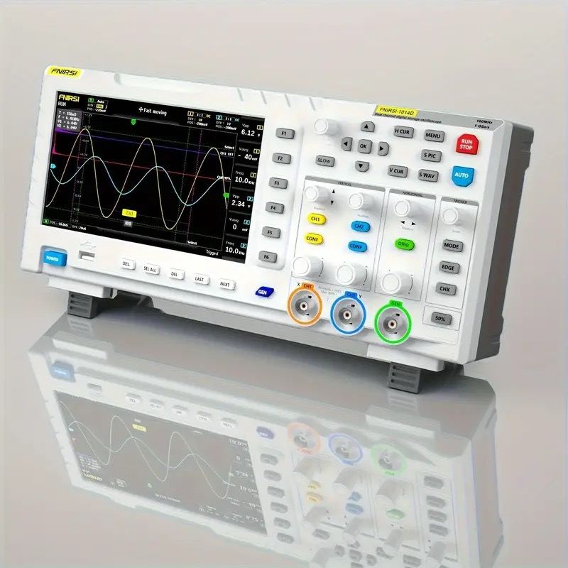
Example: If you connect the oscilloscope to a 1kHz square wave generator and measure a period of 1ms, the frequency is calculated as f = 1/T = 1/0.001 = 1000Hz.
Formulas:
- Frequency:
f = 1/T(Frequency = 1 / Period) - Amplitude: Maximum value of the waveform from the center line.
3. Logic Analyzer
A logic analyzer captures and analyzes digital signals, making it useful for debugging communication protocols like I²C, SPI, and UART. The logic analyzer provides a time-aligned view of multiple digital channels, which is helpful for analyzing the timing relationships between them.
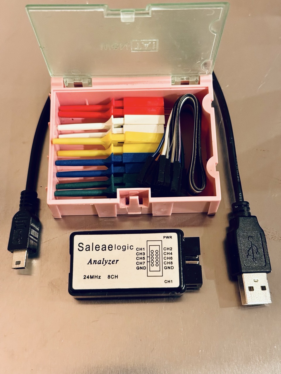
How to Use a Logic Analyzer to Analyze Digital Signals:
- Connect the probes of the logic analyzer to the relevant digital pins in your circuit, ensuring the ground clip is connected to the ground of the circuit.
- Set the sample rate to at least 10 times the frequency of the signal for accurate capture.
- Configure the trigger conditions to capture the specific event you’re interested in (e.g., the start of an I²C transaction).
- Start the capture. The logic analyzer will display the digital signals as square waves, allowing you to analyze the timing and sequence of events.
- Use built-in decoders for protocols like I²C, SPI, or UART to interpret the data streams.
Example: You connect the logic analyzer to the SDA and SCL lines of an I²C bus. The analyzer captures the signals and displays them as a time-aligned waveform, making it easy to see when the data and clock signals change.
Formulas:
- Data Rate:
Data Rate = Number of bits / Time(Bits per second or baud rate) - Timing Measurements: Measure the delay between edges (rising or falling) of different digital signals to ensure proper synchronization in communication protocols.
Tips for Using a Logic Analyzer:
- Ensure the sample rate is at least 10 times the clock frequency when working with digital signals like SPI.
- Use trigger options effectively to capture data at the correct event, such as a rising edge or specific bit pattern.
- Label channels in the software to keep track of different data lines and buses for easier analysis.
- When working with multiple protocols (e.g., UART and I²C), capture several channels simultaneously and analyze the interaction between them.
Example: While debugging an I²C communication issue, you connect the logic analyzer to the SDA and SCL lines. After starting the capture, you observe that the clock line holds low for an extended period, indicating a bus issue.
4. Frequency Counter
A frequency counter measures the frequency of an input signal, usually a repetitive waveform such as a square wave or sine wave. It's particularly useful when working with oscillators, communication circuits, or any signal source where you need to know the precise frequency.

How to measure frequency with a frequency counter:
- Connect the input probe of the frequency counter to the signal whose frequency you want to measure. The ground lead should be connected to the ground of the circuit.
- Ensure the frequency counter is set to the appropriate range or set to auto-range if available.
- The display will show the frequency of the signal in Hz (Hertz), kHz (Kilohertz), or MHz (Megahertz), depending on the signal's range.
Example: You connect a frequency counter to the clock output of a microcontroller running at 16MHz. The frequency counter reads 16,000,000Hz (16MHz).
Formulas:
- Frequency:
f = 1/T, where T is the period of one cycle.
Tips for using a frequency counter:
- Use a clean, noise-free signal for the most accurate measurement. Excess noise or distortion can cause inaccurate readings.
- Make sure the input signal is within the frequency counter's range, or use a frequency divider if needed.
- If measuring the frequency of a clock signal in a digital circuit, ensure the amplitude is high enough for proper detection.
5. Signal Generator
A signal generator (also known as a function generator) produces electrical waveforms at various frequencies, amplitudes, and shapes (e.g., sine, square, triangle waves). It is used to inject known signals into circuits for testing and diagnostics.
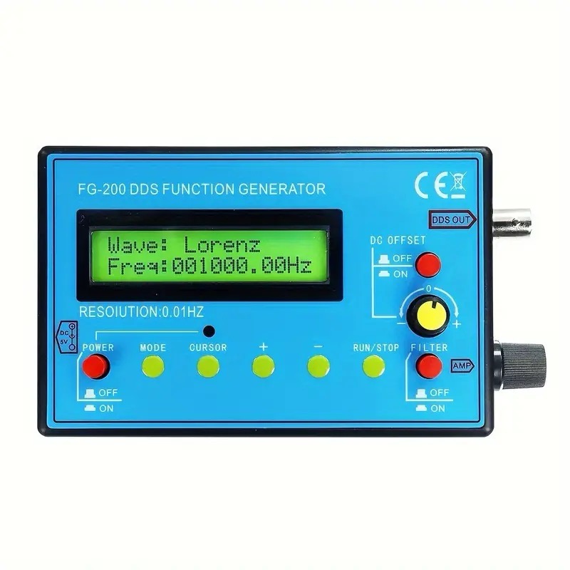
How to use a signal generator:
- Turn on the signal generator and select the desired waveform (e.g., sine, square, or triangle).
- Set the frequency using the controls or numeric keypad. For instance, set it to 1kHz for testing an audio circuit.
- Adjust the amplitude to a suitable level. Be careful not to exceed the voltage range that your circuit can handle.
- Connect the output of the signal generator to the input of the circuit you wish to test. Ensure the ground of the signal generator is connected to the ground of the circuit.
- Turn on the signal and observe how the circuit responds to the injected signal using an oscilloscope or another measurement tool.
Example: You use a signal generator to produce a 1kHz sine wave to test the frequency response of an audio amplifier. The output waveform from the amplifier is then measured with an oscilloscope.
Formulas:
- Frequency:
f = 1/T(Frequency = 1 / Period) - Amplitude: Maximum voltage level of the signal.
Tips for using a signal generator:
- Start with low amplitude and gradually increase it to avoid damaging your circuit.
- If you're testing audio circuits, the human hearing range is between 20Hz and 20kHz, so choose frequencies within that range.
- Signal generators can also create DC offsets if needed, which is useful for testing circuits that require a bias voltage.
6. Power Supply
An adjustable DC power supply is used to provide power to circuits during testing. You can set both the voltage and current to suit the needs of your project, and some power supplies have built-in protection features to prevent damage to the circuit in case of a short circuit or overcurrent.
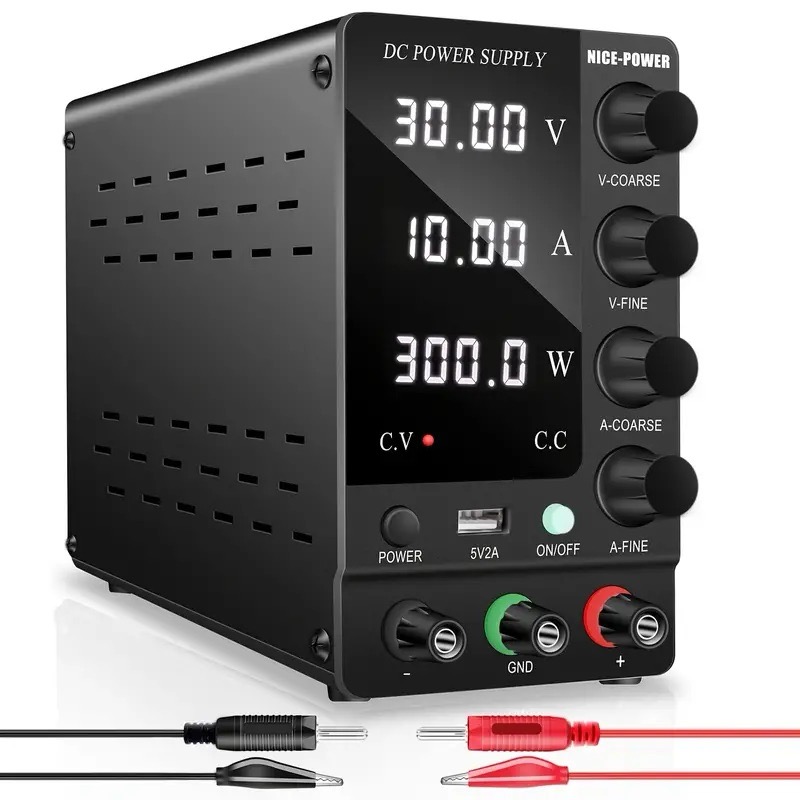
How to use a power supply to power a circuit:
- Set the output voltage to the desired level using the voltage adjustment knob or keypad. For example, set it to 5V if you’re powering a microcontroller that operates at 5V.
- Adjust the current limit to a safe value that the circuit can handle. If you're powering a microcontroller with a typical operating current of 100mA, set the current limit slightly above that, say to 200mA.
- Connect the positive (red) lead to the positive power rail of your circuit and the negative (black) lead to the ground (GND) of your circuit.
- Turn on the power supply and monitor both the voltage and current readings. The current should stay below the set limit, indicating that your circuit is functioning normally.
Example: You set the power supply to 3.3V and 500mA to power an ESP32 development board. The board operates normally, drawing around 200mA during operation.
Formulas:
- Ohm's Law:
V = I × R(Voltage = Current × Resistance) - Power:
P = V × I(Power = Voltage × Current)
Tips for using a power supply:
- Always set the current limit slightly higher than the expected current draw of your circuit to avoid false triggering of the current protection feature.
- If the current limit is reached, the power supply will reduce the voltage to keep the current below the set limit. This could indicate a short circuit or excessive load in the circuit.
- Make sure the voltage is within the operating range of all components in the circuit to avoid damage.
7. LCR Meter
An LCR meter is an essential tool for measuring inductance (L), capacitance (C), and resistance (R) in electronic components. It helps in analyzing the characteristics of passive components and verifying their values in both design and troubleshooting.
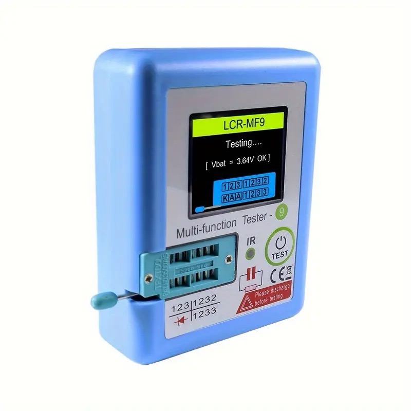
How to use an LCR meter:
- Select the desired measurement mode (inductance, capacitance, or resistance) based on the component you're testing.
- Connect the component to the meter’s test leads or sockets. Ensure proper orientation if testing polarized capacitors.
- For high accuracy, choose the appropriate test frequency if your LCR meter allows for multiple frequencies (commonly 100Hz, 1kHz, or 10kHz).
- Read the displayed value directly from the meter. Some meters also offer additional data such as quality factor (Q) and dissipation factor (D).
Example: While testing an inductor, you measure an inductance of 47μH at 1kHz. The LCR meter also provides a quality factor (Q) of 50, indicating a low loss in the inductor.
Formulas:
- Inductive Reactance:
XL = 2πfL(where f is frequency and L is inductance) - Capacitive Reactance:
XC = 1 / (2πfC)(where C is capacitance)
Tips for using an LCR meter:
- Test components out of circuit whenever possible to avoid interference from surrounding components.
- Use higher test frequencies when measuring small capacitors or inductors for better accuracy.
- If your meter shows additional values like Q factor or dissipation factor (D), use them to assess component performance in AC circuits.
8. Spectrum Analyzer
A spectrum analyzer is used to examine the frequency domain of signals, identifying the amplitude of frequencies present in a signal. It’s especially useful for analyzing radio frequency (RF) signals and electromagnetic interference (EMI).

How to use a spectrum analyzer:
- Connect the input to the circuit or antenna under test.
- Set the center frequency to the main frequency you are interested in (e.g., 433MHz for a 433MHz transmitter).
- Adjust the frequency span to view a wider or narrower range of frequencies around the center frequency.
- Analyze the signal to identify harmonics, noise, or unwanted frequency components.
Example: While testing a 2.4GHz Wi-Fi transmitter, you set the spectrum analyzer to a center frequency of 2.4GHz and observe the output power levels at various points, identifying the strongest peak at the fundamental frequency.
Formulas:
- Power in dBm:
P (dBm) = 10 × log10(PWatts) - Frequency: Measured in Hertz (Hz), identifying the signal's location on the spectrum.
Tips for using a spectrum analyzer:
- Use the narrowest resolution bandwidth (RBW) possible to increase frequency accuracy.
- Use a preamplifier to boost weak signals and increase measurement sensitivity.
- Look out for harmonics and spurious signals, which may indicate improper filtering or shielding in your circuit.
9. Network Analyzer
A network analyzer measures the transmission (S21) and reflection (S11) properties of electrical networks, usually in RF applications. It's essential for analyzing antennas, filters, and other RF components.

How to use a network analyzer:
- Connect the network analyzer to the device under test (DUT) using RF cables.
- Calibrate the network analyzer using a calibration kit to ensure accurate results for transmission and reflection measurements.
- Select the frequency range of interest and start the sweep to view S-parameters.
- Analyze the S11 (return loss) and S21 (insertion loss) data to determine the performance of the RF component.
Example: While testing an antenna for a 433MHz transmitter, you measure the return loss (S11) at 433MHz and observe a dip at the resonant frequency, indicating proper matching between the antenna and transmitter.
Formulas:
- Return Loss:
RL = -20 × log10|S11| - Transmission Loss:
TL = -20 × log10|S21|
Tips for using a network analyzer:
- Ensure cables and connectors are in good condition, as any degradation can introduce errors in measurement.
- Perform a full calibration before measuring to remove the effects of the measurement system itself.
- Use markers on the display to identify key points such as resonance frequency and bandwidth.
10. Digital Logic Tester
A digital logic tester is a handheld tool used to quickly verify the logic levels (high or low) on digital circuits. It is particularly useful for troubleshooting digital circuits like microcontrollers or logic gates.

How to use a digital logic tester:
- Turn on the logic tester and connect its ground lead to the ground of the circuit.
- Touch the probe tip to the test point on the circuit, such as an output pin on a logic gate or microcontroller pin.
- The tester will indicate whether the logic level is high (usually with an LED or sound) or low.
Example: While testing the output of an AND gate in a digital circuit, you observe that the tester shows a low logic level, indicating the gate's output is off.
Formulas:
- No specific formulas apply to a logic tester, but understanding logic levels is crucial. For example, TTL (transistor-transistor logic) systems generally define a "high" as 2.0V or above and a "low" as 0.8V or below.
Tips for using a digital logic tester:
- Ensure that the circuit is powered on when testing logic levels.
- Test multiple points along the signal path to trace where a logic error might be occurring.
- Remember that a logic tester cannot measure analog signals or timing characteristics, so it should be used for quick checks rather than detailed analysis.
Conclusion
Measuring instruments are essential tools for any electronics hobbyist or professional. By understanding how to use these tools effectively, you can diagnose and debug circuits more efficiently. Remember to always double-check your connections, use the correct settings, and apply the right formulas to interpret your measurements. With practice, using these instruments will become second nature, allowing you to build more complex and reliable circuits.


