Requirements
- Bus Pirate (any version that supports I²C)
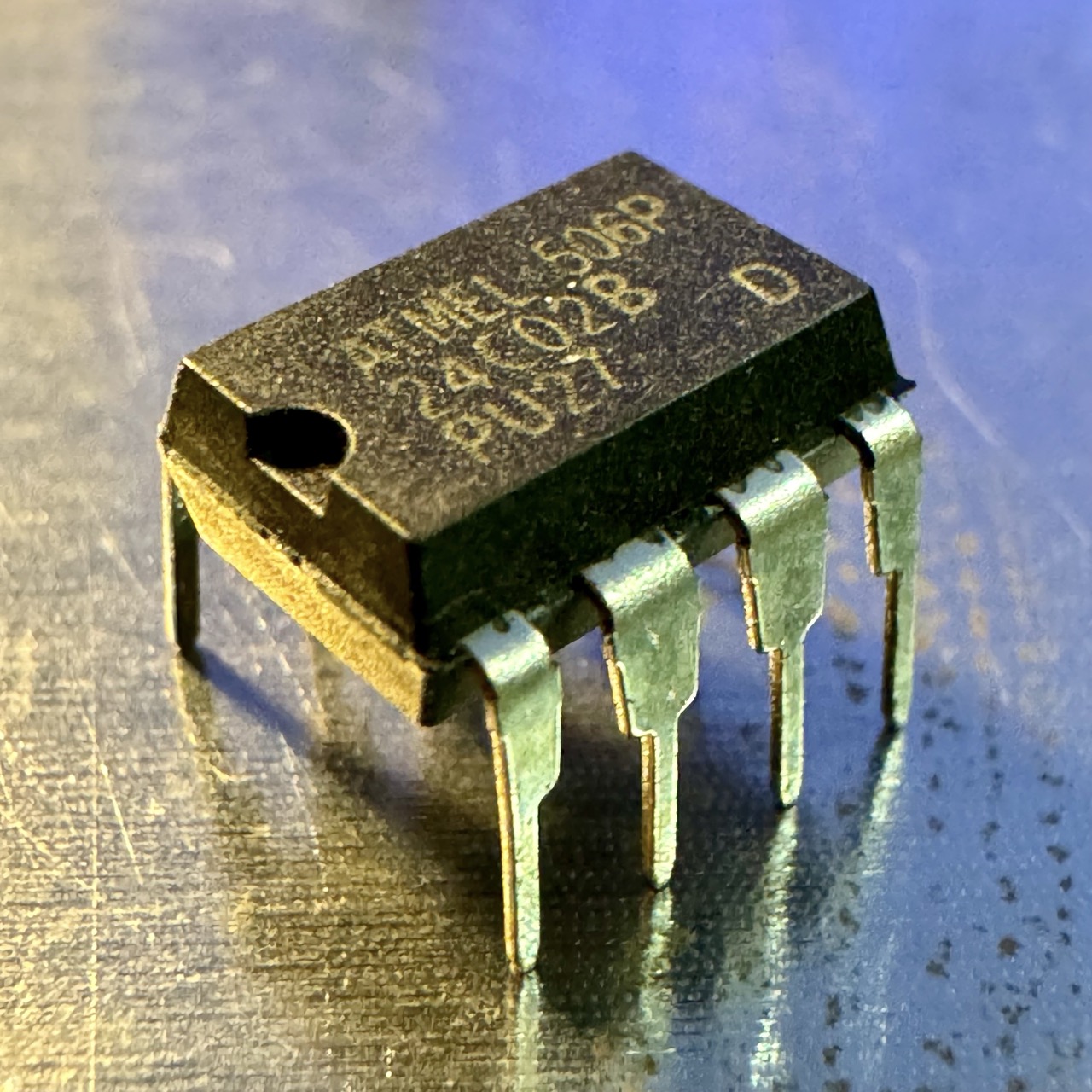
- AT24C02B EEPROM chip
- Jumper wires
- Breadboard
- Power supply (3.3V or 5V, depending on the EEPROM voltage)
- Serial terminal software (e.g., PuTTY, Tera Term, or Linux/Mac terminal)


Setup
Wiring the AT24C02B to the Bus Pirate
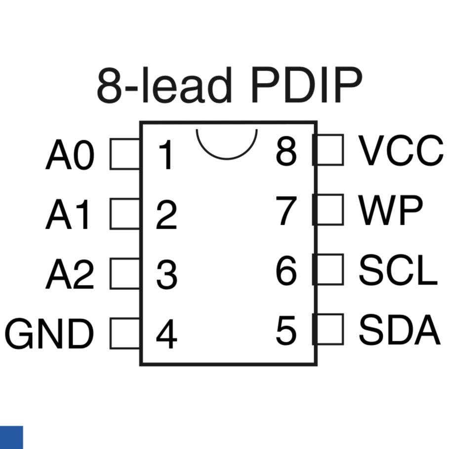
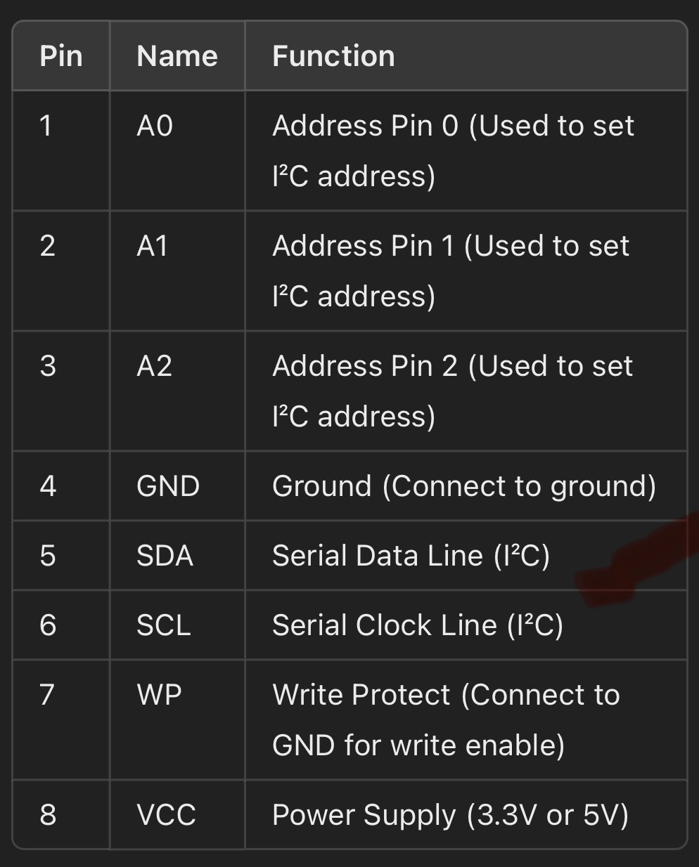
| Bus Pirate Pin | AT24C02B Pin | Function |
|---|---|---|
| 3.3V or 5V | VCC | Power supply for the EEPROM |
| GND | GND | Ground |
| MOSI | SDA | I²C Serial Data |
| CLK | SCL | I²C Serial Clock |
| CS | WP | Connect to GND (write-protect disabled) |
| (Optional) | A0, A1, A2 | Tie to GND for default I²C address (0x50) |
Note: Pull-up resistors (typically 4.7kΩ) should be connected to SDA and SCL lines. If your Bus Pirate has pull-ups, enable them via software.
Step-by-Step Guide
1. Enter I²C Mode
To enter I²C mode, type the following commands:
HiZ> m      # Enter the mode selection menu
4           # Select I²C
3           # Operate at 100 kHz (Standard mode)
You should see:
I2C>
2. Enable Pull-Up Resistors
Activate the pull-up resistors with:
I2C> p
3. Scan for I²C Devices
To scan for devices on the I²C bus, use the following command:
I2C> (1)
If the AT24C02B is connected, you should see:
I2C> Devices found: 0x50
4. Write Data to the EEPROM
To write a byte (e.g., 0x42) to address 0x00:
I2C> [0xA0 0x00 0x42]
Explanation:
- [: Start condition
- 0xA0: Write command (I²C address 0x50 shifted left + write bit)
- 0x00: Memory address
- 0x42: Data to write
- ]: Stop condition
Wait 5ms to complete the write cycle.
5. Read Data from the EEPROM
To read the byte back from address 0x00:
I2C> [0xA0 0x00]
Then, to read the data:
I2C> [0xA1 r]
You should see:
0x42
6. Perform Sequential Reads
To read multiple bytes (e.g., 4 bytes starting at address 0x00):
I2C> [0xA0 0x00] [0xA1 rr rr rr rr]
The "rr" command reads each subsequent byte, separated by repeated start conditions.
Troubleshooting
- If the EEPROM is not detected, check your wiring and ensure the correct power supply is used.
- For write errors, ensure the WP (write-protect) pin is connected to GND.
Conclusion
Using the Bus Pirate, you can easily interact with the AT24C02B EEPROM to write, read, and test data over I²C. This setup is perfect for debugging and learning I²C communication protocols.
If you need help automating this with scripts or more advanced examples, feel free to ask!
