What is a Voltage Divider?
A voltage divider is a simple circuit that uses two resistors to reduce a higher voltage to a lower one. It is commonly used in electronics to create reference voltages, measure voltages, or connect components that have different voltage levels.
Voltage Divider Circuit Diagram
The basic setup for a voltage divider consists of two resistors in series, with the input voltage applied across the pair and the output voltage taken from between the two resistors.
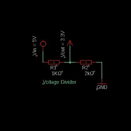
In this circuit, Vin is the input voltage, and Vout is the output voltage. The two resistors are labeled R1 and R2.
Voltage Divider Formula
The output voltage Vout can be calculated using the following formula:
Vout = Vin * (R2 / (R1 + R2))This formula tells us that the output voltage is determined by the ratio of the two resistances. By choosing appropriate values for R1 and R2, you can adjust the output voltage as needed.
Example Calculation
Let's take an example where:
- Vin = 5V
- R1 = 1kΩ
- R2 = 2kΩ
Using the formula:
Vout = 5V * (2000Ω / (1000Ω + 2000Ω))
     = 5V * (2000 / 3000)
     = 5V * 0.6667
     = 3.33V
So, the output voltage Vout is approximately 3.3V.
Components Needed with eBay Links
Step 1: Setting Up the Voltage Divider on a Breadboard
Place the resistors on the breadboard in series. Connect one end of R1 to the positive side of the power supply (Vin), and connect R2 to the ground. The output voltage (Vout) will be measured between the junction of R1 and R2.
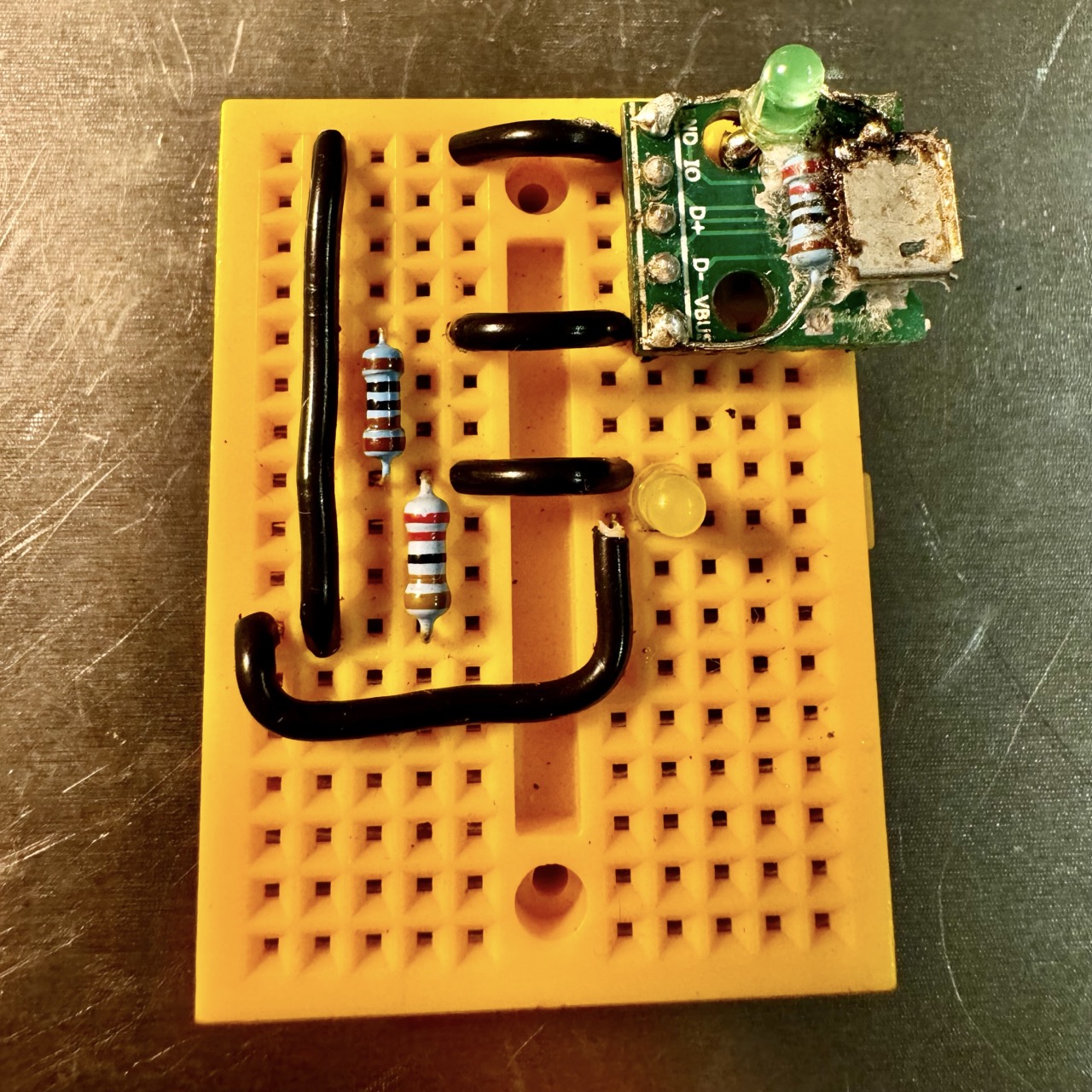
Figure 1: Setting up the voltage divider on a breadboard.
Step 2: Connecting to Power
Connect the input voltage (e.g., 5V from a USB source) across the two resistors. The positive terminal of the supply connects to the free end of R1, and the ground connects to the free end of R2.
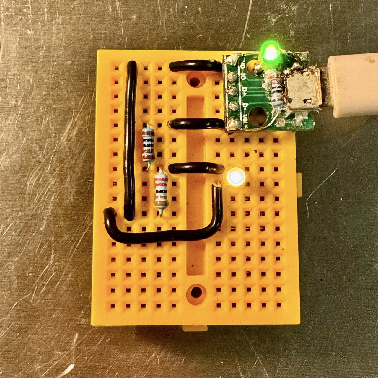
Figure 2: Connecting the voltage divider circuit to a power supply.
Step 3: Testing the Voltage Divider
Use a multimeter to measure the output voltage (Vout) between the junction of R1 and R2 and ground. The measured voltage should match the calculated value.
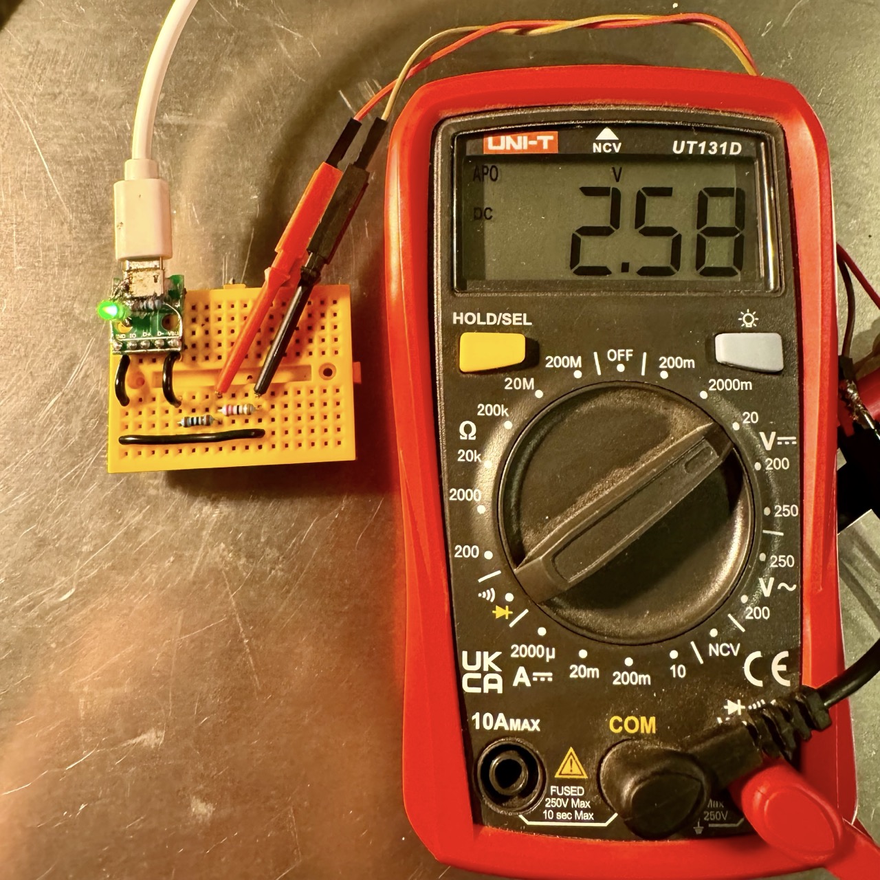
Figure 3: Measuring the output voltage with a multimeter.
Applications of Voltage Dividers
Voltage dividers are used in various applications, such as:
- Reducing high voltages to lower levels for safe measurement
- Creating reference voltages for analog-to-digital converters
- Interfacing sensors with microcontrollers that require specific voltage levels
- Adjusting signal levels in audio and analog circuits
Experiment: Try Different Resistor Values
To understand how resistor values affect the output voltage, try different combinations of R1 and R2. For example, use 1kΩ, 2kΩ, and 5kΩ resistors to see how the output voltage changes.
- Set up the voltage divider circuit as described above.
- Measure the output voltage with different resistor values.
- Record the results and compare them to the calculated values using the voltage divider formula.
Practical Examples
- 1. Voltage Divider for LED Brightness Control
- 2. Voltage Divider for Battery Level Monitoring
- 3. Voltage Divider in Sensor Interfacing
- 4. Using Voltage Divider in Analog-to-Digital Conversion
- 5. Audio Signal Level Adjustment with Voltage Divider
- 6. Using a Voltage Divider for Serial Communication
- 7. Using Voltage Divider for Reference Voltage Creation
- 8. Voltage Divider for Transistor Biasing
- 9. Voltage Divider to Interface High Voltage with Microcontrollers
- 10. Voltage Divider in Wheatstone Bridge Circuit
Conclusion
Voltage dividers are fundamental circuits in electronics, enabling the reduction of voltages for various applications. By understanding the voltage divider formula and its calculation, you can easily create circuits that interface with sensors, microcontrollers, and other components. Experimenting with different resistor values gives you a deeper understanding of how the circuit works in practice. With this knowledge, you can apply voltage dividers to a wide range of practical scenarios, including signal conditioning, reference voltage generation, and more.
Remember to always verify your calculations with real-world measurements and consider factors such as resistor tolerance and load resistance when designing circuits.
