Introduction
In this tutorial, you will learn how to use a Passive Infrared (PIR) sensor to detect motion. When motion is detected, an LED will light up, and a message will be sent to the Serial Monitor.
Objective
The goal of this experiment is to interface a PIR sensor with a microcontroller and respond to detected motion by lighting an LED and providing real-time feedback.

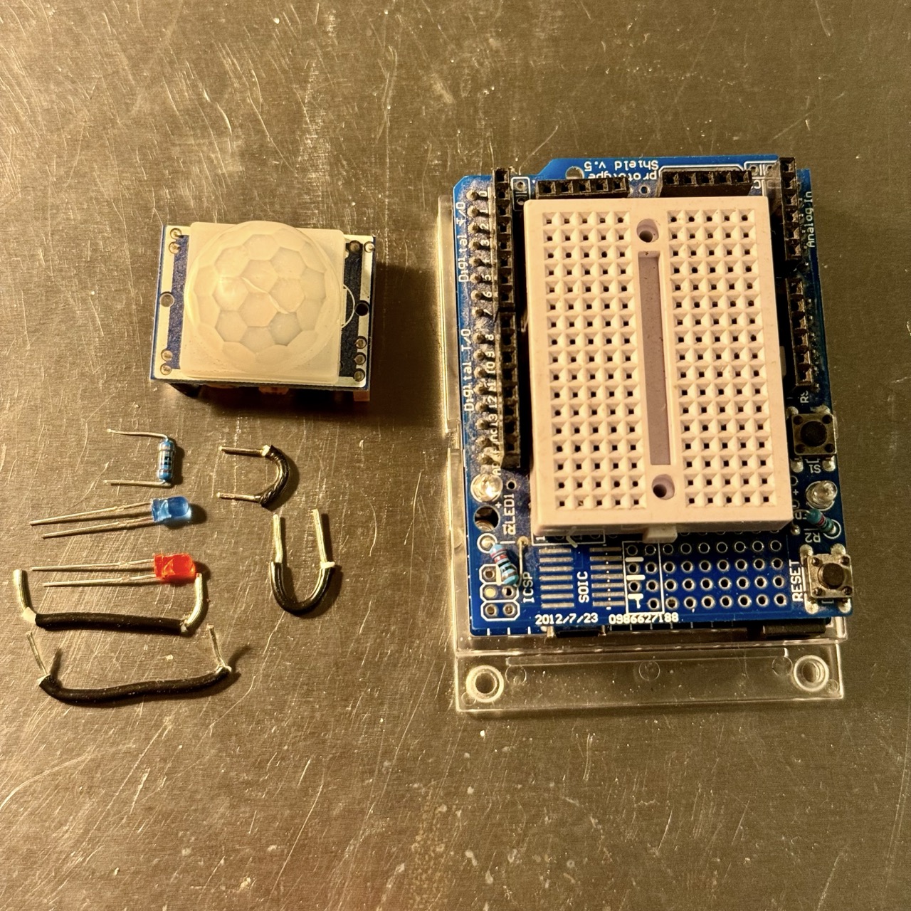
Components Required
- Microcontroller (e.g., Arduino Uno, ESP32)
- PIR motion sensor
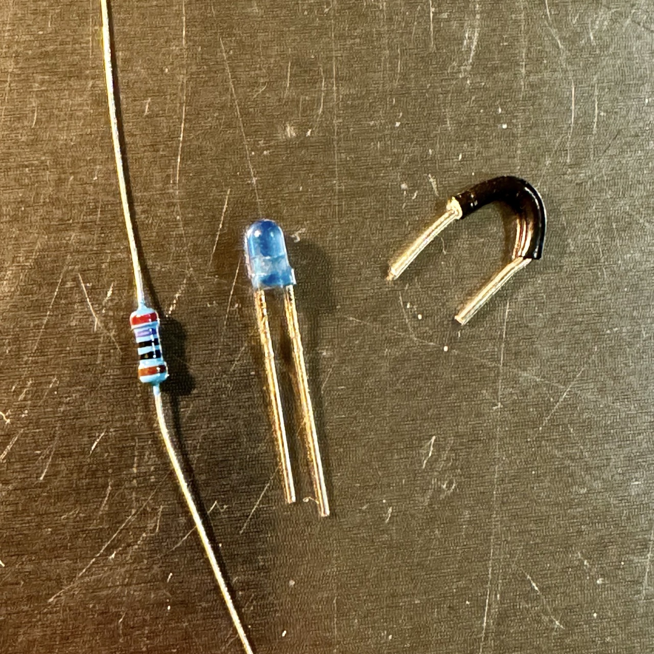
- LED
- 220 ohm resistor
- Breadboard
- Jumper wires
- USB cable for programming
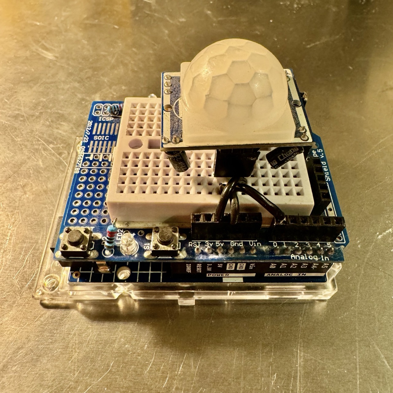
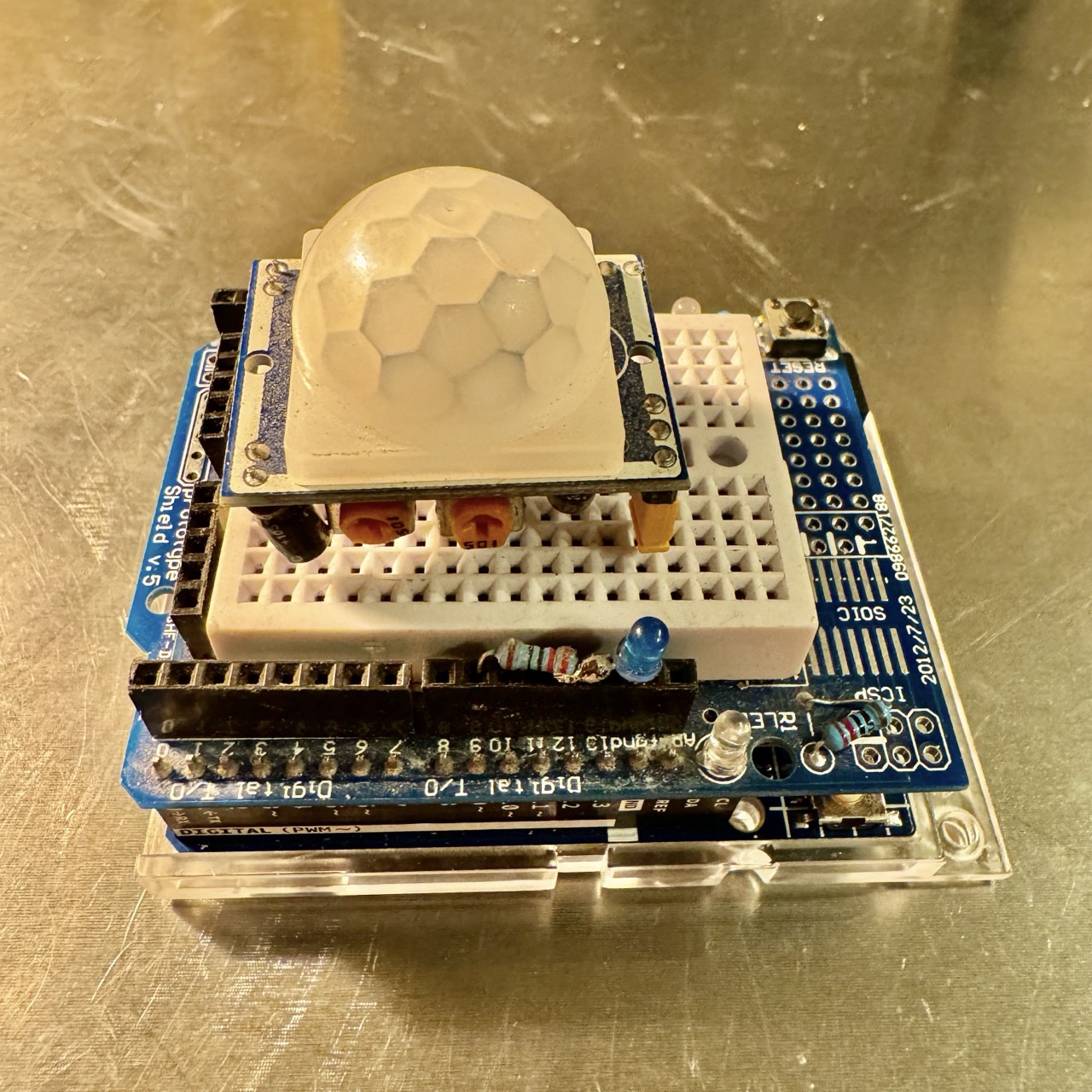
Circuit Diagram
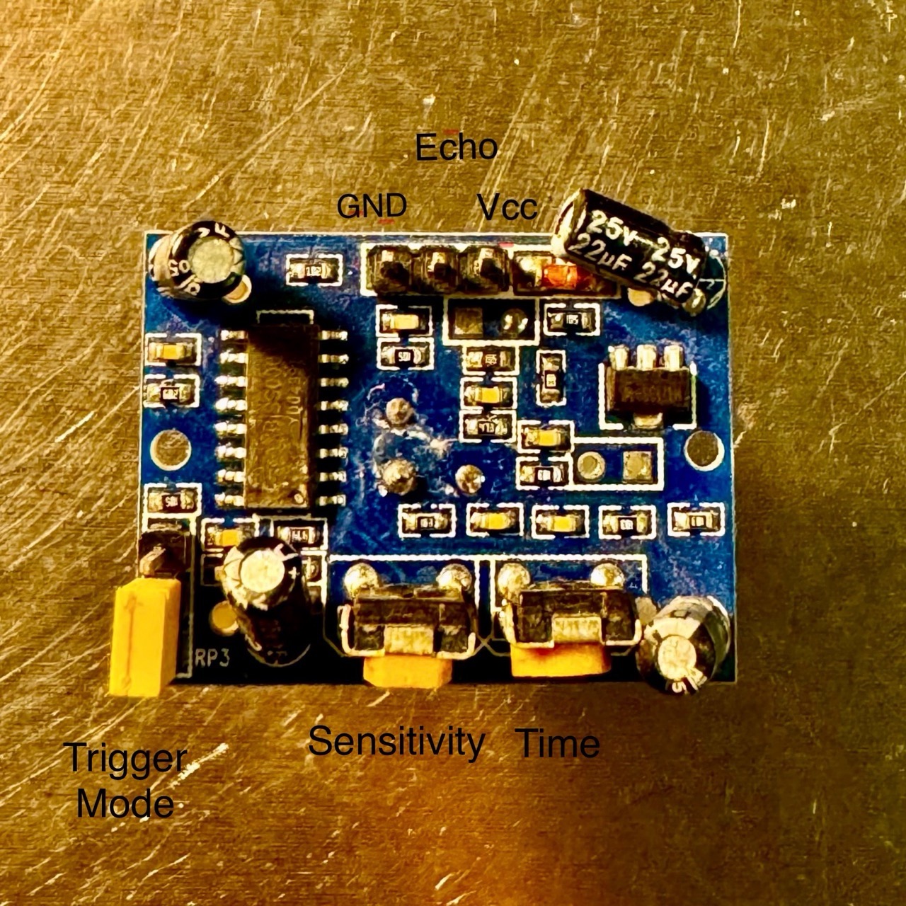
Connect the components as follows:
- VCC of the PIR sensor to 5V (or 3.3V, depending on your sensor).
- GND of the PIR sensor to GND on the microcontroller.
- OUT of the PIR sensor to A0 (analog pin).
- Connect the LED to GPIO pin 9 via a 220 ohm resistor.
Code
Use the following code to interface the PIR sensor with your microcontroller:
// Pin Definitions
const int pirPin = A0;   // PIR sensor output pin (analog pin)
const int ledPin = 9;    // LED pin

void setup() {
    Serial.begin(115200);
    pinMode(ledPin, OUTPUT);
    digitalWrite(ledPin, LOW);
    Serial.println("PIR Motion Sensor Test Initialized");
}

void loop() {
    int pirValue = analogRead(pirPin);  // Read the analog value from the PIR sensor
    if (pirValue > 500) {              // Threshold for motion detection
        Serial.println("Motion Detected!");
        digitalWrite(ledPin, HIGH);
    } else {
        digitalWrite(ledPin, LOW);
    }
    delay(100);
}
Procedure
- Connect the components as per the circuit diagram.
- Copy the code above and paste it into your Arduino IDE.
- Select the correct board and port in Tools.
- Upload the code to your microcontroller.
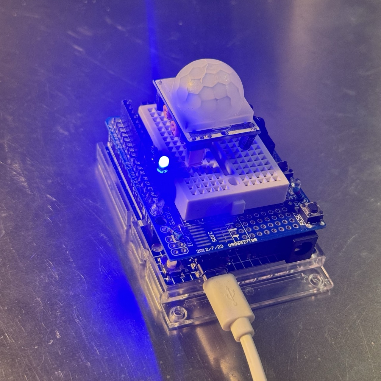
- Open the Serial Monitor and set the baud rate to 115200.
- Wave your hand in front of the PIR sensor. The LED should light up, and "Motion Detected!" should appear in the Serial Monitor.
Adjustments and Settings
Most PIR sensors have two adjustable potentiometers:
- Sensitivity: Adjusts the range of the sensor.
- Time Delay: Changes how long the output remains high after motion is detected.
Refer to your PIR sensor's datasheet for specific adjustment instructions.
Troubleshooting
- Ensure the PIR sensor is properly powered (check the operating voltage).
- Verify the connections, especially the output pin of the sensor.
- Test the sensor in a non-cluttered environment to avoid false triggers.
- Make sure the Serial Monitor baud rate matches the code (115200 in this example).