Introduction
In this experiment, you will learn how to gradually increase and decrease the brightness of an LED, creating a fading effect. This is achieved by using PWM (Pulse Width Modulation) with an Arduino.

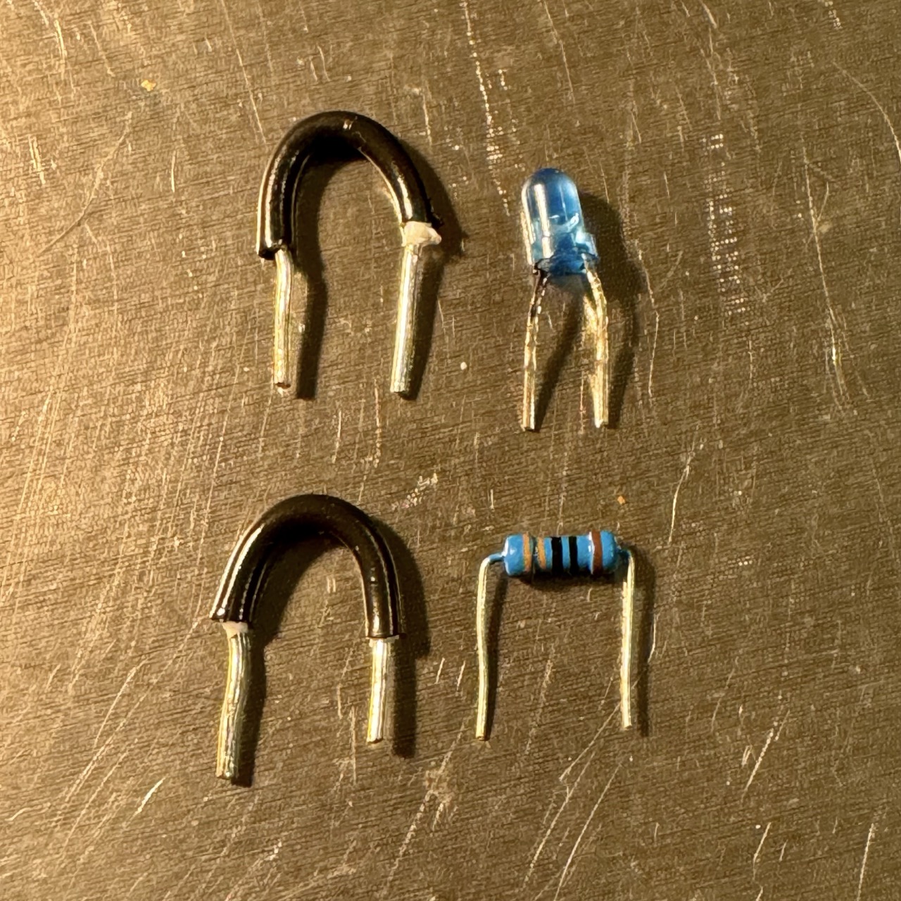
Required Components

Wiring Diagram
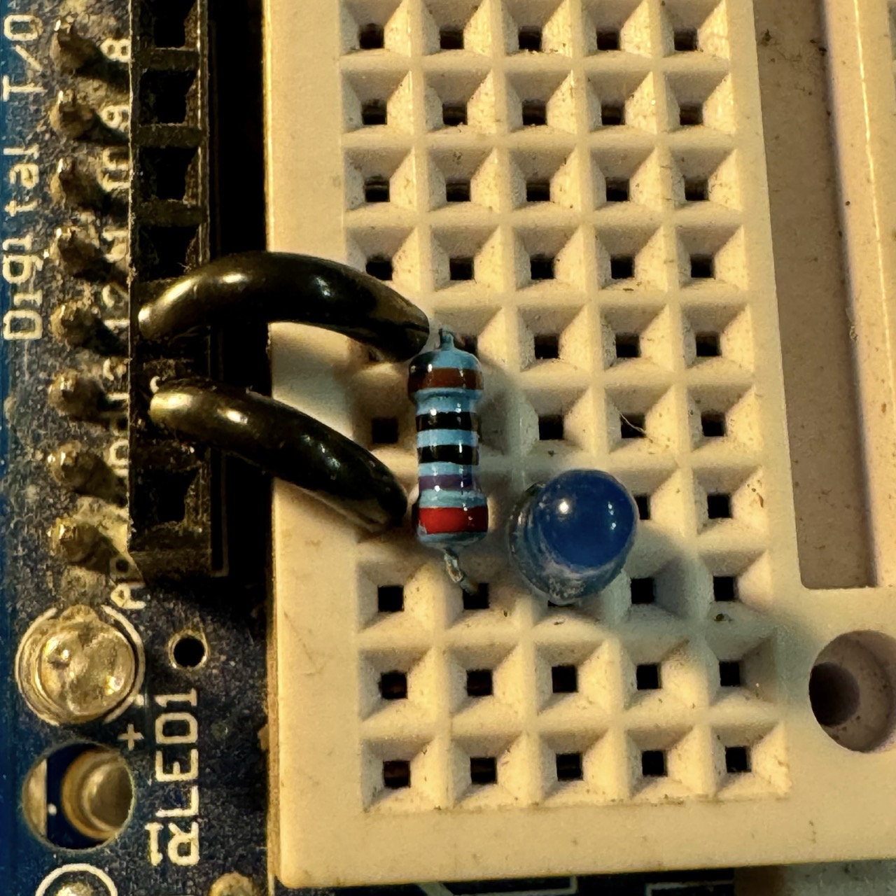
Refer to the following wiring diagram to set up the circuit correctly:

Wiring Setup
- Place the LED on the breadboard.
- Connect the longer (anode) leg of the LED to a 270-ohm resistor.
- Connect the other end of the resistor to pin 9 on the Arduino.
- Connect the shorter (cathode) leg of the LED to the ground (GND) on the Arduino.
Note: The resistor limits the current flowing through the LED, preventing it from burning out.
Code Explanation
The analogWrite() function is used to control the brightness of the LED by adjusting the duty cycle of the PWM signal sent to pin 9. Here’s how the code works:
- The first
forloop gradually increases the brightness from 0 (off) to 255 (fully on), creating the fade-in effect. - The second
forloop decreases the brightness from 255 to 0, creating the fade-out effect. - The
delay(10)function controls the speed of the fade; you can adjust it for faster or slower fading.
Arduino Code
Copy the following code into the Arduino IDE and upload it to your Arduino board:
// Define LED pin
int ledPin = 9;

void setup() {
    pinMode(ledPin, OUTPUT);
}

void loop() {
    // Fade in the LED
    for (int brightness = 0; brightness <= 255; brightness++) {
        analogWrite(ledPin, brightness);
        delay(10);  // Adjust this delay for faster/slower fading
    }

    // Fade out the LED
    for (int brightness = 255; brightness >= 0; brightness--) {
        analogWrite(ledPin, brightness);
        delay(10);
    }
}
Upload & Test
Once the circuit is wired and the code is uploaded to the Arduino, observe the LED gradually brighten and dim. If the LED doesn’t work as expected, refer to the troubleshooting section below.
Troubleshooting
- If the LED does not light up, check the wiring and ensure the LED is connected correctly.
- If the LED stays on constantly without fading, verify that the correct pin (9) is specified in the code and connected properly in the circuit.
- Ensure you are using a resistor to protect the LED from excessive current.
Conclusion
This experiment demonstrates how to control an LED's brightness using PWM with Arduino. By mastering this technique, you can create dynamic lighting effects for your electronics projects, such as mood lighting, LED displays, or decorative effects for your home or workspace.
The concepts of PWM and analog control go beyond LEDs and can be applied to various components like motors, servos, or even audio signals. For example, PWM can be used to control the speed of a DC motor or adjust the position of a servo motor with precision.
If you're new to Arduino, this project is an excellent stepping stone for understanding the basics of programming and electronics. As you gain confidence, you can experiment with more complex circuits, add multiple LEDs, or even incorporate sensors like light or motion detectors to make your projects interactive.
Here are a few ideas to extend this project:
- Use multiple LEDs with different colors to create a multi-channel fading effect.
- Add a potentiometer to adjust the fading speed dynamically.
- Integrate a light sensor to make the LED brightness adapt to ambient light levels.
- Combine this effect with an RGB LED to create smooth color transitions.
We hope you enjoyed this project and learned something new about Arduino and PWM. Keep exploring and experimenting—there's no limit to what you can create with Arduino!
